This page is not made for printing. For a printed copy, use the light PDF: https://xor.eu/downloadfiles/nerdseq/manual/nerdseq-manual-light.pdf
XOR Electronics · Eurorack
NerdSEQ
Hybrid Tracker Sequencer, Synthesizer and Toolbox
User Manual
Firmware V3.03
This is an ever-growing manual. Save the trees by not printing it out!
If you really can’t resist, there is a light version made for printing: nerdseq-manual-light.pdf.
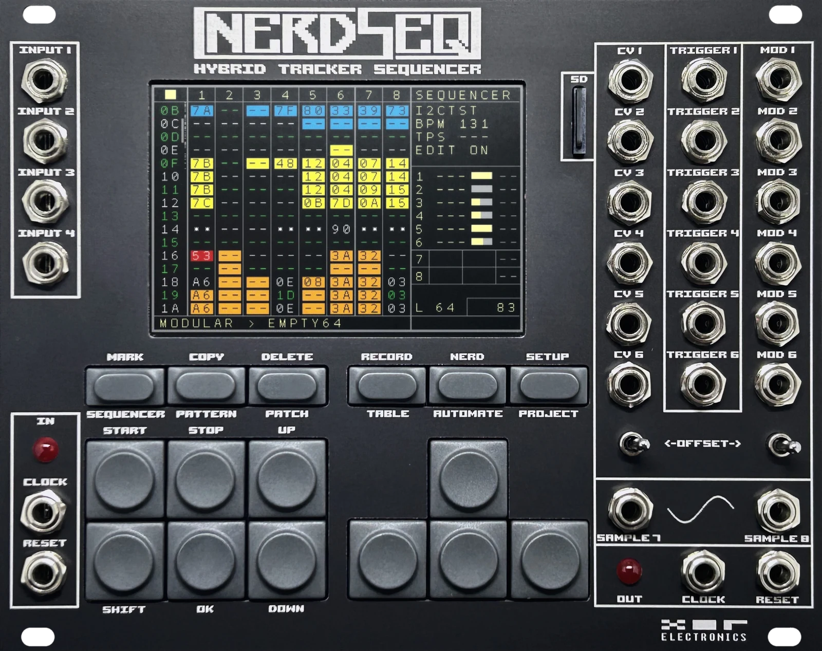
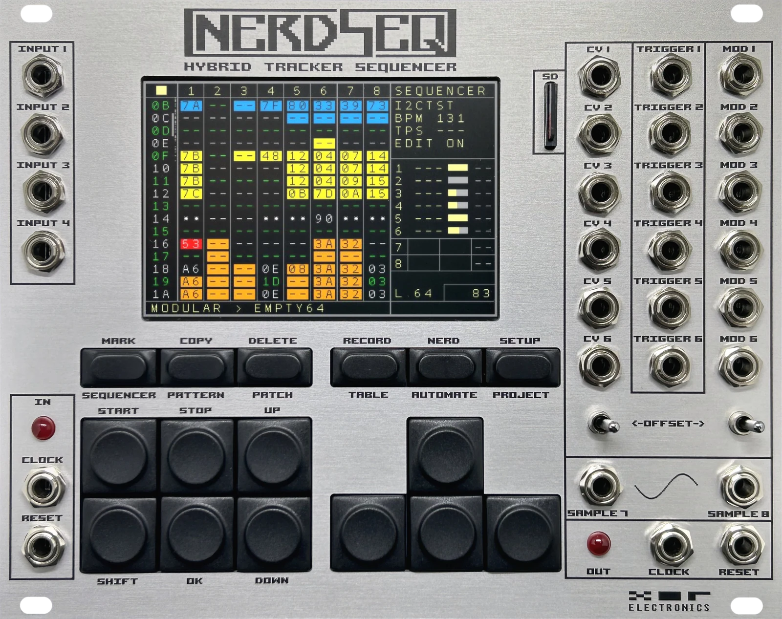
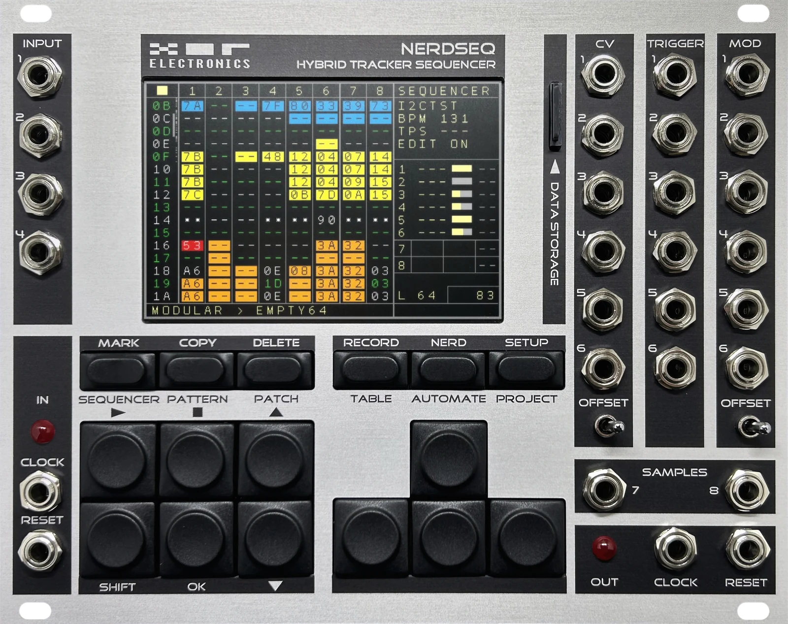
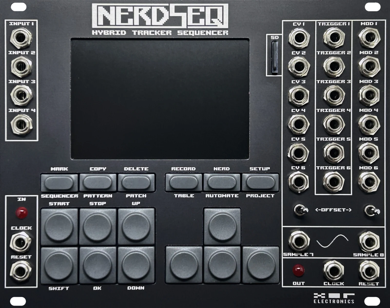
01
Introduction
The NerdSEQ is a tracker-based sequencer, synthesizer and modulation generator for Eurorack systems.
It has 8 tracks which can be used for CV/Gate, MIDI, I2C sequencing and more. In the basic configuration, the first 6 tracks generate CV, trigger and gate signals on 18 outputs (12 CV + 6 trigger/gate). The other 2 tracks are audio tracks, each with 2 dedicated audio parts for sampling and synthesis sequencing. The audio part can also act as a waveform oscillator or FM synthesizer.
- 1CV1 · TRIG1 · MOD1
- 2CV2 · TRIG2 · MOD2
- 3CV3 · TRIG3 · MOD3
- 4CV4 · TRIG4 · MOD4
- 5CV5 · TRIG5 · MOD5
- 6CV6 · TRIG6 · MOD6
- 72 audio parts → SAMPLE 7
- 82 audio parts → SAMPLE 8
Every track can also be switched to another function:
- MIDI Midi expanders
- More CV outputs CV16
- More trigger outputs Trigger16
- I2C Multi-IO
- Multi-oscillator Dualchord
- Video synthesizer Video Expander
Modulation functions such as LFOs, envelopes and many more complex functions can be generated for internal and external use. Dedicated clock and reset inputs and outputs are available for different clock types. 4 freely assignable CV inputs can be used for live manipulation or CV/Gate recording. An advanced modulation matrix, which also allows algorithmic functionality (a kind of scripting), connects all kinds of internal and external signals with each other.
The sequencer itself is inspired by old module trackers1 like Fasttracker 2 (PC)2, OctaMED (Amiga)3, LittleSoundDJ (Game Boy)4 and Little Piggy Tracker (multiple platforms)5, to name only a few. There are many more inspirations.
It contains many functions for sequencing: advanced live performance, pattern lengths up to 64 steps, chaining, polyrhythmic tracks, groove, glide, retrigger, flexible trigger, gate and step lengths, patches, special effects, probability, advanced timelines, tables and much more. The audio tracks add sample playing, pitching, sample effects and retrigger, as well as a synthesizer engine that creates waveforms or acts as a 4-operator FM synthesizer. Samples are loaded from the SD card slot on the front panel.
The sequencer can make loops (as in many loops) and full songs — even several songs in one project, depending on complexity and how many patterns they use. Patterns can be started and stopped independently per track, which allows flexible clip-style sequencing. Projects are saved to and loaded from the microSD card.
All editing is implemented in a very easy way (at least I tried to make it so). Every screen or edit option can be reached with one key or SHIFT + key. There are no nested submenus and no deep menu diving, and I try to keep it that way in future updates.
Additional expanders allow MIDI recording and sequencing, control from a Sega gamepad, up to 64 more trigger, gate and CV outputs, virtual patch cables over I2C, sequencing for the ART modules by Tiptop, a flexible 8-voice oscillator/synth voice, and screen cloning and video synthesis on a composite or HDMI screen.
In general, you can go very deep with the NerdSEQ. There are so many features that it can feel overwhelming, and not everything will be easy to understand at first. You don’t have to use everything. Start simple and explore more features along the way. And when you wonder whether the NerdSEQ can do this or that, chances are high that it can, often in more than one way. It is worth reading through the manual, or at least the parts that interest you.
So don’t get scared: you have a very powerful tool in front of you, and it only gets as deep as you want it to.
 1
2
3
4
5
6
7
8
9
10
11
12
13
- CV inputs 1–4 0–10 V, freely assignable
- Clock and reset inputs with the IN clock LED
- Display 480 × 320 colour IPS
- microSD slot projects and samples
- CV outputs 1–6
- Trigger/gate outputs 1–6
- MOD outputs 1–6
- Offset switches for CV and MOD
- Audio outputs 7 and 8
- Clock and reset outputs with the OUT clock LED
- Screen buttons second function with SHIFT
- Transport and edit buttons
- Cursor keys
All expanders connect on the back of the NerdSEQ with ribbon cables: the Midi expanders with a 12-pin cable to the PAD-Midi port, the NSA expanders with a 14-pin cable to the NSA header. The ART add-on is the exception and hangs off an I2C port of the Multi-IO.
- 1
 2
 3
 4
 5
 6
 7
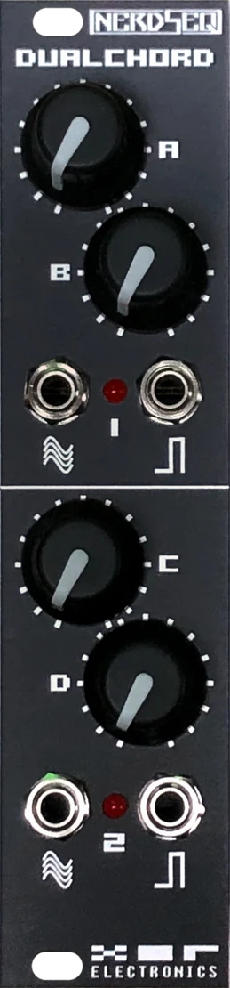 8
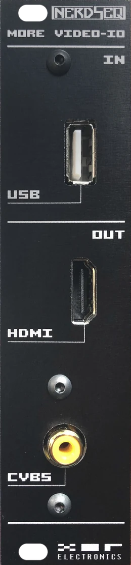 9
 10
- NerdSEQ 32 HP. The sequencer itself; everything else on this page plugs into its back.
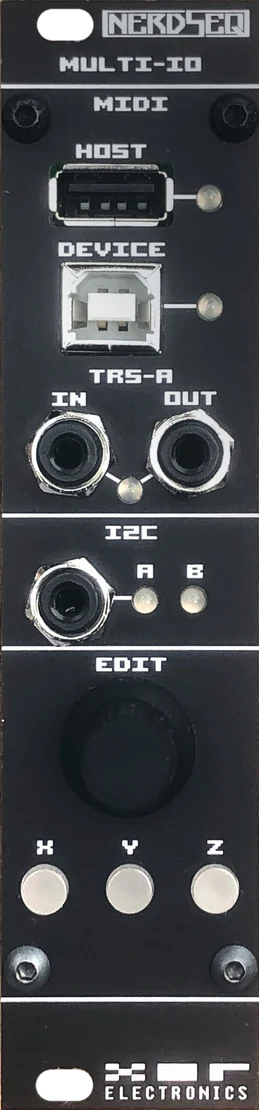
- Multi-IO 6 HP. Three independent Midi ports (TRS-A, USB Host, USB Device) and two I2C ports.
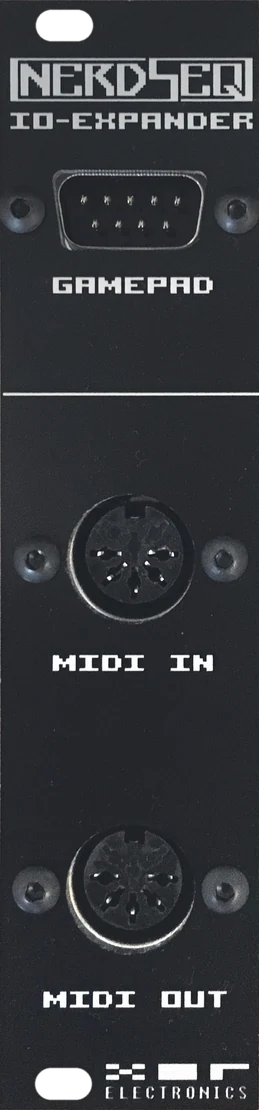
- Midi-IO 6 HP. The classic Midi expander: Midi in and out, plus a Sega Gamepad port.
- TRS-A Midi 2 HP. The Midi-IO without the Gamepad port: TRS-A in, out and thru.
- Gamepad 4 HP. A Sega Gamepad port on its own, for the NerdSEQ or the Multi-IO.
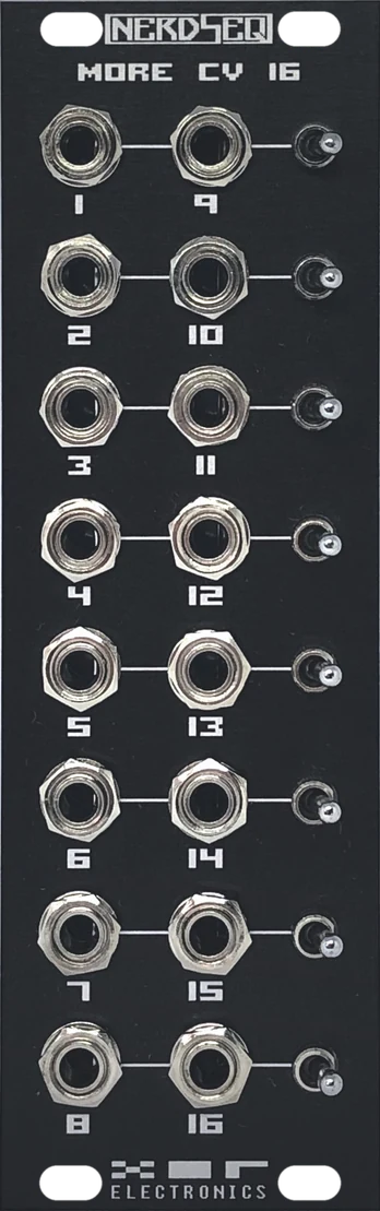
- CV16 8 HP. 16 more CV outputs, with 8 envelopes and 8 LFOs to route to them.
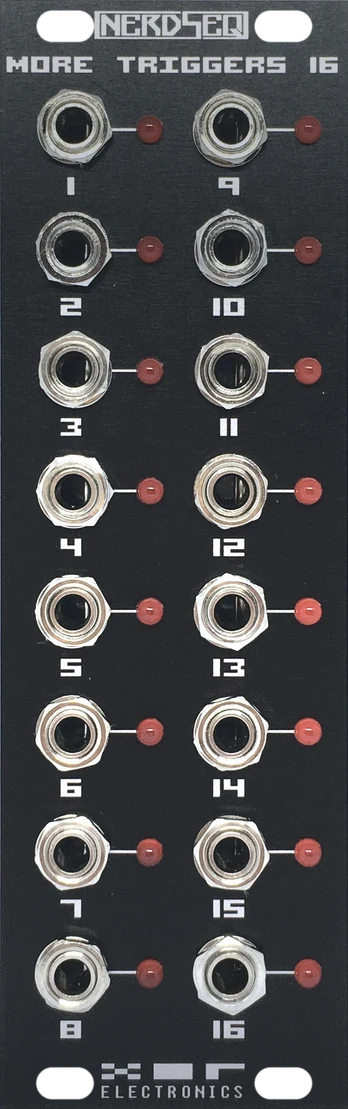
- Trigger16 8 HP. 16 more trigger/gate outputs, each with its own LED.
- Dualchord 6 HP. Two audio outputs, each driven by four digital oscillators.
- Video Expander 6 HP. HDMI and composite video out with a video synthesizer, and USB for a PC keyboard.
- ART add-on 2 HP. Two ART outputs for TipTop ART modules; needs the Multi-IO.
02
Technical specification
Power, panel and connectors.
Power consumption
28 mini-jacks (mono)
| 4 | CV inputs | 0 to 10 V |
|---|---|---|
| 2 | Clock + reset inputs | 5 V |
| 12 | CV outputs (CV 1–6, MOD 1–6) | −5 to +5 V or 0 to +10 V |
| 6 | Trigger/gate outputs | 5 V |
| 2 | Audio outputs | −5 to +5 V, AC coupled |
| 2 | Clock + reset outputs | 5 V |
Hardware overview
| Front panel | Grey/silver, black, or combined grey/black |
|---|---|
| Display | Colour graphics IPS wide-angle display, 480 × 320 pixels |
| Buttons | 10 full-size and 6 half-size buttons |
| Switches | 2 toggle switches to change the offset of the CV voltages |
| LEDs | 2 LEDs to indicate clocks |
| Storage | microSD connector, accessible on the front panel |
| Power connector | 10-pin boxed bus connector |
| MIDI expander | 12-pin boxed expander connector for the Midi expander modules |
| NSA expander | 14-pin boxed expander connector for special NerdSEQ extensions (NSA) |
03
Firmware features
What the firmware does, grouped by area.
- 8tracks
- 255sequencer rows
- 176patterns, up to 64 steps each
- 144patches
- 32tables, up to 16 steps each
- 12sample slots
- ∞possibilities
Sequencing
- Tracker-style sequencer
- 8 tracker tracks, controlled independently, synchronised or unsynchronised
- Polyphonic sequencing per track
- 255 sequencer rows
- 176 patterns with up to 64 steps each
- 144 patches
- 32 tables (a sequencer in the sequencer) with up to 16 steps each — for transpose, scaling, different speed/note scales and sources, synchronised or unsynchronised to the main sequencer clock, with randomisation functions
- ‘Endless’ pattern chaining
- Multiple playback types per track: forward, backward, pingpong, random, snake, spiral, even, odd and more
- All Modular tracks can be manipulated from other tracks
- Advanced note scaling with many scale presets and user scales
Steps, rhythm and chance
- Patterns with note-scaled input, patch selection, trigger/gate with retrigger, delayed triggers etc., CV modulation manipulation, groove, fine pitch, glide, glide quantisation, table selection…
- Multiple direct FX per pattern per step
- Groove per step per pattern for different step lengths, shuffle and weird rhythms, and for polyrhythmic tracks
- Euclidean input for rhythm composing
- Drum matrix with up to 16 drum-trigger points at the same time per track
- Probability (0–100 % in 1 % steps) for a sequencer row or for dedicated functions: CV, Mod, Trigger/Gate, Tables, Samples and FX (which can contain every feature)
- Advanced ratcheting settings
- Trigger functions with different timings for ON/OFF, OFF/ON (delayed gate) and retriggering
- Gate length as short or long as needed (much shorter than the step length is possible)
Clock and CV
- Clock source: internal, 1/16 via clock input, 24 ppqn, MIDI clock, DIN Sync
- Clock outputs: 1/16, DIN Sync, MIDI clock
- Track dividers and multipliers: /32, /16, /8, /7, /6, /5, /4, /3, /2, ×2, ×3, ×4, ×5, ×6, ×7, ×8
- CV outputs generate 1 V/Oct, 1.2 V/Oct and Volt/Hz
- CV recording
- Free record routing for CV and MIDI input
- Free routing of CV inputs to different functions
Modulation
- 8 automation slots for LFOs, envelopes, noise, randomness and more, freely connected to internal and external parameters via a modulation matrix
- 8 ADSR envelopes with rich setup, source and destination functionality
- Modulation matrix (Mapping) where all features can modulate each other
- Mapping also allows scripting and algorithmic creations
Audio tracks
- 2 × 2 sample parts for the 2 sample/oscillator/synthesizer outputs (mono)
- 12 sample slots
- 180 kB 8/12-bit sample memory (4 seconds at 44.1 kHz, 8-bit mono, or longer at lower sample rates)
- Sample support for RAW 8-bit mono and WAV 8/16/24/32-bit, mono/stereo
- Sample, wave and synth pitch in note scale
- Audio effects: volume, fine pitch, retrigger, backwards, bitcrush, distortion, offset, wavefolder, audio delay…
- Waveform oscillator with multiple waveforms on the audio outputs
- 4-operator FM synthesis between waveforms, with dedicated FM synth functions
Live and editing
- Flexible live player to switch between different patterns (clips) on different tracks
- Live mode to trigger, mute and solo patterns
- Live editing while playing, including pattern creation, manipulation and recording — nearly all functions are accessible while playing
- Advanced mark, copy and paste to copy marked parts within or between patterns
- Pattern cloning
- Patch cloning
MIDI and expanders
- MIDI sequencing and recording, including 4 polyphonic notes per track, velocity, CC, pitch bend, program change, channel and polyphonic aftertouch, NRPN and more
- Expander support for up to 64 more outputs and/or extra functionality
- Video Expander to show the NerdSEQ screen on a monitor, TV or projector
- Video synthesis with shaders (with the Video Expander)
Files
- Project management
- Sample management
- As many projects as the SD card can hold
… and many more features.
04
Firmware versions
This manual is valid for the following firmware versions.
| Module | Firmware |
|---|---|
| NerdSEQ | V3.03 |
| Multi-IO | V1.2 |
| Video Expander | V3.03 |
| Dualchord | V1.4 |
| CV16 | V1.2 |
| Trigger16 | V1.1 |
I recommend using the latest versions so that all features are available across the NerdSEQ ecosystem.
05
Basic overview
How the function blocks of the NerdSEQ relate to each other.
Several functions can manipulate each other, which helps to create complex sequences. In the most basic case, the sequencer selects a pattern to play on a track. That pattern sequences notes, triggers and so on into one of its destinations, for example the CV/Gate outputs or samples.
On top of that, these sequences can be further manipulated by the Automators or the Tables, for example. Some functions can also be routed to outputs without any sequence: an envelope can go directly to a CV/MOD output, and the envelope itself can again be triggered or gated by a sequence, a table, the CV inputs or other sources.
The Mapping block can access and manipulate all of the blocks in all directions. This ranges from something as simple as mapping a MIDI CC to a CV output up to complex algorithmic processing across several blocks. You can even ‘code’ games with it that use any of the signals or modulations.
06
Getting started
Power up, and what the NerdSEQ does before the first screen appears.
-
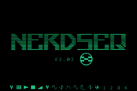
Splash screen
First there is a splash screen, followed by the current firmware version number.
-
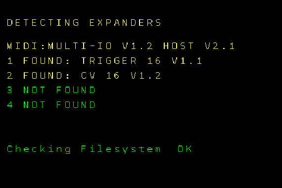
Expander check
The system checks whether any NSA (Nerd Sound Adapter) expanders are connected. If so, it shows their type and firmware version. Channels with nothing connected show as
Not Found. -
SD card check
The SD card is checked to confirm it is correctly initialised.
-
Ready
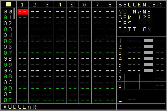
The start-up sequence is finished, and an empty Sequencer screen waits for you to get started.
| Expander | Detected at start-up |
|---|---|
| NSA expanders | Automatically, with type and firmware version |
| Midi-IO, TRS-A | Not detected, but work immediately |
| Multi-IO | After you enable it once in the Setup screen; from then on it is detected and shows its firmware versions |
| Video Expander | After you enable it in the Setup screen (clone mode); it then shows up as the 4th NSA (needs Video Expander firmware V3.0 or higher) |
Next comes a guide to the basics of values that you will find in most trackers, then some basics about trackers and navigation on the NerdSEQ.
07
Numbers, values and tracker basics
Reading a tracker: rows, columns, note names and hexadecimal numbers.
The history of trackers7 goes back to the late 1980s, when people developed a new way of making music by entering the score differently. It is often seen as programming music rather than composing, because of the way the music data is entered. That is not really the case: once you know the basics, it is composing all the way!
Trackers are often used to play samples (in a note scale) on different tracks, and to control the sound chips of old home computers directly. The workflow differs from score-based or piano-roll sequencing.
In most trackers the sequence runs from top to bottom, in rows and columns. Each row is a step in the sequence. The main columns are the tracks, and sub-columns hold different commands. Each track usually has the same kind of sub-columns (modern trackers allow different kinds of tracks and sub-columns): typically one for the note, one for the volume and sometimes one for a special command, plus more depending on the tracker.
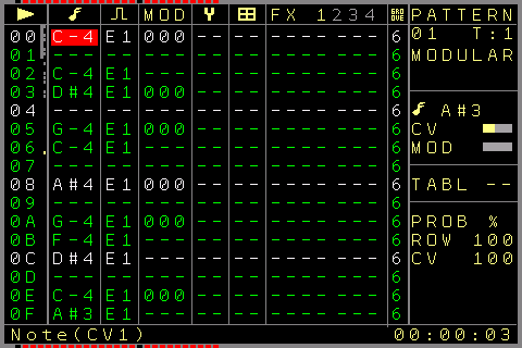
Notes are written as the note name followed by the octave:
C-3- note C, octave 3
F-5- note F, octave 5
D#2- D sharp, octave 2 — a semitone above
D-2 Eb2- the same note shown as a flat
The NerdSEQ can also show flat note values on demand, selectable per track: instead of D#2, the same note is shown as Eb2. The exact look of notes differs between trackers; on the NerdSEQ they look like the examples above.
Hexadecimal
Other values in the sub-columns, such as the volume, are usually shown as hexadecimal8 numbers. Only the very basics are explained here; the footnotes link to more detail.
We usually count in base 10: 0, 1, 2 … 9, 10, 11 … On every 10th number the digit on the left increases; on every 100th, the two digits on the left, and so on. Hexadecimal is base 16, so the left digit increases on every 16th number. Instead of reaching 10 after 9, the letters A to F fill the gap:
- 0
- 1
- 2
- 3
- 4
- 5
- 6
- 7
- 8
- 9
- A
- B
- C
- D
- E
- F
- 10
- 11
- 12
- …
- 19
- 1A
- 1B
- …
| Dec | Hex | Dec | Hex | Dec | Hex |
|---|---|---|---|---|---|
| 0 | 0 | 16 | 10 | 32 | 20 |
| 1 | 1 | 17 | 11 | 33 | 21 |
| 2 | 2 | 18 | 12 | 34 | 22 |
| 3 | 3 | 19 | 13 | 35 | 23 |
| 4 | 4 | 20 | 14 | 36 | 24 |
| 5 | 5 | 21 | 15 | 37 | 25 |
| 6 | 6 | 22 | 16 | 38 | 26 |
| 7 | 7 | 23 | 17 | 39 | 27 |
| 8 | 8 | 24 | 18 | 40 | 28 |
| 9 | 9 | 25 | 19 | 41 | 29 |
| 10 | A | 26 | 1A | 42 | 2A |
| 11 | B | 27 | 1B | 43 | 2B |
| 12 | C | 28 | 1C | 44 | 2C |
| 13 | D | 29 | 1D | 45 | 2D |
| 14 | E | 30 | 1E | 46 | 2E |
| 15 | F | 31 | 1F | 47 | 2F |
So after 9F comes A0, and after FF comes 100. The NerdSEQ shows most of its values in hexadecimal.
Screens instead of scrolling
Some trackers show all content on one screen; others need scrolling, and some switch to a different screen for other content. Because the NerdSEQ has a small display, the information is divided logically into different screens, explained later on.
There is much more to know about trackers — the links below are a good start. I also suggest looking at some tutorials for LittleSoundDJ, as it is the tracker most similar to the NerdSEQ. Though there are some major differences, it gives a good idea of how to work with dedicated screens.
08
Buttons and navigation
You navigate, switch screens and edit values with the buttons. Most of them have a second function with SHIFT.
Screen buttons
The 6 half-size buttons on the top row switch between screens. Hold SHIFT and press one of them for its second function.
| Button | Opens | With SHIFT |
|---|---|---|
| SEQUENCER | Main sequencing: pattern arrangement, song structure etc. | MARK — start marking content on the screen. Press again to copy the marked values to the clipboard. |
| PATTERN | The pattern data: all the notes, gates and effects. | COPY — copy previously marked (or cut) content into the new position. Also copies marked values to the clipboard. |
| PATCH | The stored patches (macros), the current values of the current track, or the track setup. | DELETE — delete the current value or the marked content. Acts as cut for marked values. |
| TABLE | Tables: a sequencer in the sequencer, running synchronised with or independently from the main sequence, and able to manipulate it in many ways. | RECORD — start/stop recording. |
| AUTOMATE | Automators/modulators that manipulate many parameters through LFOs etc. Press again to toggle between the Automator and the Envelope screen. | NERD — different functions, like a context menu. In most cases, SHIFT + NERD twice opens the Mapping screen. |
| PROJECT | All project-related settings. Toggles with the Video Expander Project screen if a Video Expander with firmware V3.0 or higher is installed. | SETUP — the Setup screen, for general settings that are not tied to a project. |
Bottom-left buttons
- START
- Start the sequencer, or trigger/cue a pattern.
- STOP
- Stop a pattern; with SHIFT, stop the sequencer. If the sequencer is already stopped, SHIFT + STOP runs ‘Stop All Sounds’: all gates are reset, all notes stopped, and a reset signal is generated if the clock output is a regular modular clock. On an audio track, pressing STOP on a track that is already stopped stops all sound on that track.
- SHIFT
- Reach the second function of a button, or edit.
- UP
- Page up by 16 steps: the cursor moves 16 rows up.
- DOWN
- Page down by 16 steps: the cursor moves 16 rows down.
- OK
- Mostly used to create new patterns or patches, and to enter, confirm or start a menu option.
Cursor keys
The cursor keys are on the right. Up, down, left and right do simple navigation and scrolling, and work like this in most screens: in the Sequencer screen, for example, ▲/▼ change the row and ◀/▶ change the track/column. Some screens have more key combinations, explained later on.
Editing values
Combined with SHIFT, the cursor keys edit. Values always change in the smallest steps with SHIFT + ◀/▶ and in bigger steps with SHIFT + ▼/▲. In the Pattern screen:
| Keys | Note | Value up to FF (255) | Value above FF | FX type |
|---|---|---|---|---|
| SHIFT + ◀ / ▶ | −/+ 1 semitone | −/+ 1 | −/+ 1 | −/+ 1 |
| SHIFT + ▼ / ▲ | −/+ 1 octave | −/+ 16 ($10) | −/+ 64 ($40) | −/+ 10 |
- If Editsteps are enabled (Setup screen), the cursor moves down automatically by the edit step amount when you insert a value with SHIFT + ▲ on an empty field in the Pattern screen.
- SHIFT + DELETE deletes/empties values.
- SHIFT + MARK starts Mark mode in the Pattern or Sequencer screen. Select a block with the navigation buttons: navigating with SHIFT moves the start point of the block, without SHIFT the end point. Press SHIFT + MARK again to leave Mark mode and copy the marked values to the clipboard. There are more functions in Mark mode and with the MARK button, described in the relevant parts of the manual.
Mute and solo
| SHIFT + DOWN + START | Mute/unmute the current track (Sequencer or Pattern screen). Muting releases the gate and keeps the CV voltage, and nothing else plays on the track until it is unmuted. A muted track keeps sequencing in the background and the Break command still works, so a 16-step pattern stays 16 steps long even while muted. |
|---|---|
| SHIFT + UP + START | Solo/unsolo the current track: all tracks are muted and the current track is unmuted if needed. Unsoloing unmutes all tracks. Unmuting another track, or muting the solo track, also releases the solo. |
| SHIFT + UP + START ×2 | Unmute all tracks quickly. |
The same mute and solo functions work in the drum matrix of an I2C/Multi track or the Trigger16 expander.
Quick navigation
- In the Pattern screen, hold PATTERN and use the cursor keys to move between patterns, in the order of the sequencer arrangement.
- In the Table screen, hold TABLE and use ▲/▼ to move between tables.
09
General screen information
The workflow is divided into screens. You will spend most of your time in two of them.
Most screens have a frame containing the main clock and cue indicator, either horizontally or vertically. If the main clock is based on 64 steps, for example, it shows the currently playing step as a kind of progress bar. Many screens also have a status bar at the bottom with extra information about the function under the cursor.
- SEQUENCER
Sequencer
Your track arrangement. From here you sequence the patterns.
- PATTERN
Pattern
Notes, FX and more for each step — the main sequencing.
- PATCH
Patch
Patches (macros) run from a pattern step; also current values and track setup.
- TABLE
Table
The sequencer in the sequencer, run from a pattern step.
- AUTOMATE
Automator · Envelope
LFOs and other modulation sources; 8 ADSR envelopes.
- PROJECT
Project
Load/save, tempo, transpose; entry to Scale, Track assign, MIDI/I2C setup, clock.
- SHIFT+SETUP
Setup
Editor and hardware settings, calibration, expander firmware.
- SHIFT+NERD
Nerd menu
A context menu to change functions and values quickly.
- SHIFT+NERD ×2
Mapping
Connect anything to anything, from mod matrix to algorithms.
Sequencer and tracks
The main screen is the Sequencer screen, which shows your track arrangement and patterns. You can sequence each of the 176 patterns on any track, as long as the track has the same type — patterns differ depending on the track type. A Modular track has its strength in sequencing the CV/Gate outputs and their modulations, for example, while a MIDI track is specialised in polyphonic MIDI sequencing. There are 8 pattern/track types, each with its own sequencing strengths:
- Modular
- Audio
- Midi
- Trigger16
- CV16
- Dualchord
- I2C/Multifunctional
- Video
Patterns, patches and tables
Each pattern has its own Pattern screen with the note values, FX and much more — the main sequencing. On each step, a pattern can also execute patches (like macros) or tables (a sequencer in the sequencer). These have their own Patch and Table screens. There are 144 patches and 32 tables in total.
A pattern is locked to its track type. It can be re-used on other tracks of the same type, but not on tracks of a different type; the editor prevents selecting patterns that are not allowed. Tables and patches are also related to the track type, and are ignored (or limited) on other track types.
Each track type has its own track setup screen for track-specific functions. Another screen shows the basic current values of a track and lets you change them by hand.
Menus and settings
The Nerd menu is a context menu that opens in many places, to execute or change functions and values quickly.
The Project screen holds project-related settings. Load and save your projects there, and change global settings such as the global transpose or the project BPM. It is also the entry point to other project-related screens: the Scale screen for all your quantisation needs, Track assign, MIDI routing in the Midi Setup/I2C screen, clock input/output settings, and more. Project screen settings are saved and loaded with the project.
The Setup screen holds the editor, functionality and hardware settings that you usually change once, or at least not often. You can also calibrate there and update the expander firmware. These settings are stored in the hardware automatically and survive a power cycle.
Modulation
The Automator screen is one of the side screens for modulation. It contains LFOs and other modulation sources, and a basic modulation matrix that sends the automator results to many track-related destinations. For envelopes, there are also 8 ADSR envelopes in the Envelope screen.
The Mapping screen is another major command centre. There you can combine all kinds of internal and external parameters: just connect them mod-matrix style, or add algorithmic manipulation, up to generative processes. Or, if you can, code that one missing function yourself.
Even though there are many screens and menus, you will mostly work in the Sequencer and Pattern screens. The important screens are reachable with one button or a double press.
10
Sequencer screen
The main screen: the pattern arrangement of all 8 tracks. Press SEQUENCER to get there.
- Play and record indicator
- Row numbers
00–FE - Scrollbar and mini-map of all 255 rows
- Tracks 1–8
- Cursor
- Pattern number in a slot
- Empty slot
-- - Screen name
- Project name, tempo, global transpose, editor on/off
- Recent note, gate/trigger and modulation of the 6 CV/Gate tracks
- Audio tracks: recent samples or waveforms
- Length of the pattern under the cursor
- Status text
- Time since playback started
- Main clock indicator
Rows and tracks
The sequencer screen is for the general sequencing of patterns. Here you combine islands or chains of patterns into loops or songs.
The leftmost column shows the row numbers, from 00 to FE (255 rows), next to a scrollbar (yes, you can scroll all the way down) and a mini-map that shows, for all 255 rows, whether a row uses any patterns. You always see 16 rows at a time; the screen scrolls as you navigate.
The next 8 columns are the 8 tracks. By default each track is dedicated to one output channel — track 1 to CV1, TRIGGER1 and MOD1, and so on — so with the default settings there are 6 CV/TRIGGER/MOD tracks and 2 Audio tracks.
Some slots are empty (shown as --), and some have patterns filled in. If track 1 shows 00 in the first row, pattern 00 is assigned to that spot. The same pattern can appear in two tracks if those tracks are of the same type. Several instances of the same pattern number stacked below each other play that pattern several times.
A ** in a slot stops the track (not the sequencer) when the player reaches it. Starting a ** slot by hand also stops the track. Use it to start only some of the tracks in a row, or to stop several tracks at once.
Navigate with the cursor keys. If ‘Navigation Wrap’ is enabled, the cursor wraps around from the rightmost position.
Playing
| START | Start playing the selected pattern, or the first (top) assigned pattern. This starts one track only. |
|---|---|
| SHIFT + START | Start the whole row. While playing, it triggers the whole row to play next. |
| START while playing | Cue the selected pattern: it plays after the current pattern in the same column has finished (Normal launch mode) or on a zero crossing of the main clock (Sync launch mode). |
| START ×2 | Trigger the next pattern sooner, after the number of steps set by the project setting ‘Live Cue-points’ (derived from the main clock steps). The next start point shows on the main clock indicator. |
| STOP | Stop the pattern after it has finished; no other pattern plays on this track afterwards. |
| STOP ×2 | End the pattern on this track immediately. |
| SHIFT + STOP | Stop the player, send a reset pulse on the reset outputs and reset all gates (and, if enabled in the settings, all effect values). With the sequencer stopped, this is the ‘Panic’ function: a note-off to all MIDI devices and a new reset pulse. |
Chained patterns (one below the other) play in sequence and loop back to the start of the chain at its end.
You can also mark several tracks with SHIFT + MARK. START or STOP then starts or stops the selected tracks in the same launch mode (START uses the first marked row).
Creating and entering patterns
| OK on an empty slot | Create a new, empty pattern with a new number. On a filled slot, OK either enters the pattern or does nothing, depending on the setting. |
|---|---|
| SHIFT + OK | Clone the pattern under the cursor: its content is copied completely into a new pattern. |
| SHIFT + DOWN + OK | Clone into a new pattern placed in the row below, and move the cursor there. Existing content in that row is overwritten by the cloned pattern number. |
| SHIFT + OK in Mark mode | Clone the whole marked area, as long as there are free patterns. Free unused patterns with the Clean Patterns function in the Reorganize screen. |
| SHIFT + ▶ | Re-use an existing pattern: browse to the pattern number with SHIFT + ◀/▶. |
| PATTERN or OK | Enter the pattern under the cursor (OK if enabled in the Setup). More in the Pattern screen chapter. |
Every position in the Sequencer screen can have its own colour, to help you recognise patterns or blocks more quickly. Apply colours to a single position or a marked block in the Nerd menu.
The information panel
On the right you see the project name, the tempo, the current global transpose and whether the editor is enabled. The editor can be disabled so that no pattern can be changed by accident — while playing live (triggering patterns), for example, or giving a demonstration.
In the middle are indicators for the recently played notes, the gate/trigger state and the modulation state of the 6 CV/Gate tracks. Extra indicators show when a track uses a different clock (multiplier/divider, or decoupled from the clock: EX) or a playback order other than the default (numbers highlighted). Below are the 4 audio parts, showing the recently playing samples or waveforms, followed by a decimal view of several values (if enabled). To the left of it is the length of the selected pattern (cursor on a pattern).
At the bottom is a status text with useful information — mostly the type of the current track, or the pattern’s name if it has one. At the bottom right is the time elapsed since playback started.
Copy and delete
Three buttons copy and delete sequencer content: MARK marks an area to copy or delete, COPY copies or inserts a previously marked area at another row/column, and DELETE empties or deletes the marked area (or the current cursor position).
- Press SHIFT + MARK on the start position. The screen border changes colour to show Mark mode.
- Move the cursor to the end of the area. Hold SHIFT while navigating to move the start position instead.
- Press SHIFT + MARK again (or SHIFT + COPY). Mark mode ends and the block is in the clipboard.
- Move the cursor to the destination and paste, in one of two ways:
The block is copied to the cursor and replaces what was there.
The block is inserted; the rows below shift down. (DOWN is the page button, not the cursor key.)
Copying onto an incompatible track type (a Modular track onto an Audio track, for example) leaves the destination unchanged, to avoid problems caused by track incompatibilities.
Deleting a single position
Empties the current position.
Really deletes the position; the following rows move one up.
Inserts an empty spot; the column shifts one row down.
Deleting a block
- Press SHIFT + MARK on the start position (the border changes colour).
- Move the cursor to the end of the area.
- Empty it with SHIFT + DELETE, or delete it with SHIFT + UP + DELETE — the rows below move up and fill the space.
Deleting marked values also copies them to the clipboard, so delete works as cut-and-paste.
11
Tracks and patterns
Each of the 8 tracks (technically the 8 columns in the Sequencer screen) can be dedicated to sequencing specific destinations. For example, you would use a Midi track type to create polyphonic Midi sequences, while you would use a Modular track type for dedicated CV and Gate sequencing. Each track type is specialised to emphasise the possibilities of the selected destinations.
The track type decides which columns a pattern has and what they can do, so that every column fits its job. A Modular track, for example, has dedicated columns for the CV, the trigger and the modulation output. A Midi track instead has 4 note columns, each with its own velocity, for 4-voice polyphonic Midi sequencing per track, and functions that only make sense for Midi, such as note off with release velocity. That is why every track type has its own Pattern screen, its own list of FX commands and its own Track Setup, all described below. The possible destinations per track are:
- CV/Gate (Modular track) which has dedicated functions for the local CV and Gate outputs.
- Samples / Oscillators / FM Synth (Audio track) has features for playing samples, waveforms, or building an FM synthesizer
- Midi (Midi track) has its strength in polyphonic MIDI sequencing and Midi effects, controllers etc. You need a Midi Expander(there are 3 different types) for MIDI sequencing.
- Trigger16 is a special track type for the Trigger16 expander, which has special trigger columns and a drum matrix to trigger up to 16 different drums/triggers per track
- CV16, for the CV16 expander, which has 16 more CV outputs that can be sequenced or manipulated polyphonically, as well as its own envelopes and LFOs
- Dualchord for the Dualchordexpander, which has dedicated columns and commands to sequence up to 8 paraphonic waveforms of the Dualchord multi-oscillator.
- Multi/I2C which is a combination of different destination types. As the name suggests, it allows all possible I2C sequencing, and far beyond that it can be used for many different purposes, including most of the other track type destinations (e.g. CV, Midi, Triggers…). It also has a drummatrix, just like a Trigger16 track but here each of the drummatrix columns can be assigned to either trigger outputs, Midi, I2C and more.
- Video for the More Video-IO expander which has all the functionality for advanced video synthesis.
By default, tracks 1 to 6 are set up as Modular tracks and tracks 7 and 8 as Audio tracks. Only tracks 1 to 6 can be Modular tracks, and only tracks 7 and 8 can be Audio tracks; all the other types can be used on any track. To change the assignment, use the Track Assign screen, which you can access from the Project Screen (Project Screen Track Assign Screen).
Track Assign Screen
In the Track Assign screen you can assign different track types such as CV/Gate, Midi, or Trigger16 to one of the tracks. You can enter the track assign screen from the project screen.
PROJECT SCREEN→TRACK ASSIGN
The Track Assign screen shows 8 rows, one for each of the 8 tracks. The types of the tracks can be changed by using SHIFT+CURSOR LEFT/RIGHT. This allows you to choose between the Modular track type (only for Tracks 1..6), NSA1,2,3,4 → and if there are expanders connected, then it shows the recognised expander type (Trigger16, CV16, Dualchord, Video) together with the NSA Channel number, Midi and, lastly, I2C/Multi. Tracks 7+8 don’t allow you to choose a modular track; instead you can select them to be audio tracks (samples, oscillators, FM Synth) or the NSA, Midi or I2C track types.
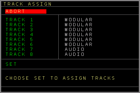
When you are done with the assignment, choose SET and press OK, and the tracks will be assigned. (If you leave the screen and forget to SET, it will ask you to confirm or abort the changes.)
If a track has already been assigned, you can also enter the track setup screen of the track here by using the OK button.
Track Setup Screen
Here you can change track-specific and track-type-specific settings. Some settings are common to all tracks (e.g. Track Clock, Pattern Order) and some are specific to the track type (e.g. Column Destinations, Oscillator settings etc.).
You can enter the track setup screen in the following ways:
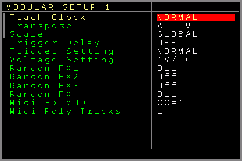
- via the Nerd Screen / Menu on the sequencer screen
- via Track Assign Screen (press the OK button on one of the already assigned tracks)
- by pressing the PATCH button while in the Current Values Screen (pressing PATCH twice from the Sequencer Screen or in most parts of the pattern screen gets you to the Track Setup screen).
The track-type-specific settings are explained within the pattern screen descriptions.
These are the common settings available for all track types:
- Track Clock → Change clock dividers or multipliers of the track. If the player is playing, the change applies at the end of the current pattern. If it is not playing, the change is applied immediately. Change using SHIFT+CURSOR LEFT/RIGHT.
The Track Clock can be set to the following Multipliers/Dividers: /7,/6,/5,/3,/32,/16,/8,/4,/2,Normal, *2,*4,*8,*3,*5,*6,*7
The lowest setting called Mapping will decouple a Track from the Mainclock and the track clocks/ticks can be fed from a Mapping Destination (TRACK → Track X → TICK). Here you can feed the track manually with ticks from any source, such as the CV inputs, Midi/I2C, or any NerdSEQ parameter. Any Mapping source can serve as a tick source. Check the Mapping Screen for the possibilities.
- Transpose → Allows or prevents transposing of the track. This applies to both the global and the track transpose.
- Scale → Set either to the global scaling (define the global scale in the Scale Screen / Settings), or select to bypass scaling so that no scale setting has any effect on the track’s playback/editing. It is also possible to select one of the 89 different scales or a user scale just for this track.
- Trigger Delay → Delays the Trigger on the local Trigger output with a fixed or a random time (compared to the CV change of the track). Depending on the setting Setup Screen→Trigger Delay reach this applies only to the trigger column or to all generated triggers.
This is useful for modules that do not sample the CV voltage correctly after the rising edge of the trigger. A value of 0 means that the triggers have no delay.
Beyond the maximum delay time (16.9 ms), 16 random ranges can also be selected as a variable trigger delay. Use these to achieve a humanisation effect. (Press OK on one of the random ranges to enter the Random Ranges Screen and change the range).This setting is only functional on tracks 1..6.
- Trigger Setting → Either Normal or Inverted. When Normal is selected, the Trigger/Gate behaves normally (Off = 0 Volt, On = 5 Volt). If Inverted is selected, the Trigger/Gate output is inverted: → Off = 5 Volt, On = 0 Volt.
This setting is only functional on tracks 1..6.
- Voltage Setting → Defines the type of voltage output:
- 1V/Oct
- 1.2V/Oct (Buchla scaling)
- Hz/Volt (old analogue synth scaling)
This setting is only functional on tracks 1..6.
- Random FX1..4 → Enables randomised values for the selected FX. When turned on with a range selected, all FX values in that column will play with random values within the selected ranges. This can also be toggled with the Random FX command (RDMN) from the FX list. Press OK to get to the Random Ranges Screen and change the ranges.
Note that some track types have only 2 or 3 FX columns and therefore only 2 or 3 Random FX settings.
Basic Pattern Screen info and editing functions
The following general pattern functions and info apply to all pattern types.
All pattern screens (which differ depending on the track type) share some common visual elements. In the first column from the left side you can see the different pattern row numbers. Within this field you can see the current playback position on the left side which shows the current playing step. To the right of the row numbers there is the scrollbar which shows the current cursor position within the complete pattern. Next to that is a little mini-map which shows for the whole pattern if any values are filled in. If the player is playing and the current pattern is playing, then a little indicator is running and showing the current step within this mini-map. The middle part mostly contains track-specific columns like notes, triggers, FX etc. On the right side there is mostly an info-column which gives some info about the pattern and some current states. The different Pattern Screen explanations for the different track types go into the details of these.
- Navigate with the cursor keys to left/right for the columns and up/down for the rows
- If ‘Navigation Wrap’ is enabled in the settings, the cursor will jump back to the top when the bottom is reached. Likewise, when the cursor reaches the rightmost position, it will go back to the leftmost position, and vice versa.
- START starts or cues the current pattern.
SHIFT+START starts or cues the whole row of the sequencer screen (if you entered the pattern screen on the 2nd row of the sequencer screen, then the 2nd row is affected) - Using the Nerd Menu (SHIFT+NERD), you can also name a pattern.
- In the setup menu you can change the highlighting period (e.g. every 4th row is highlighted).
- Extra editing features if not marked:
Remove the current row and shift everything below the row one up: SHIFT+UP+DELETE
Insert an empty row and shift everything below the current row one down: SHIFT+DOWN+DELETE
- You can browse between different patterns by holding the PATTERN button and using the cursor keys. This will navigate between the patterns as they are arranged on the Sequencer Screen.
PATTERN + CURSOR LEFT/RIGHT will browse through the sequencer row/tracks and select any available pattern there to be edited directly. And PATTERN + CURSOR UP/DOWN will browse through the patterns on the same track as they are lined up in the sequencer screen.
- When the cursor is on an FX command, you can open the FX Selector by pressing OK.
A menu appears showing all possible effects for this track type. You select an effect with the OK button and it will be filled into the FX command column.
- There are several facilities to copy, delete or manipulate pattern content. For that there are the 3 Buttons MARK, COPY and DELETE. (use these alternate button functions while holding the SHIFT button).
MARK to mark an area which should be copied, manipulated or deleted (use SHIFT+DOWN to mark all), COPY to copy/insert a previously copied area to another row/column and DELETE to empty or delete the marked area (or to delete/empty the current cursor position). Deleting also copies the deleted values to the clipboard, so it can function as a Cut + Paste operation.
To Copy a block:
Press SHIFT+MARK on the first position which should be copied (Screen border colour should change to indicate the Mark mode)
Move the cursor to the last position of the desired area (press SHIFT+DOWN to mark all).
The start position of the mark can be changed when holding the SHIFT button when navigating.
Press SHIFT+MARK (or SHIFT+COPY) again. Mark mode is released and the marked block is saved to the clipboard.
Now move the cursor to the destination position.
There are 2 ways to copy:
1st Press SHIFT+COPY and the previously saved block is copied to the current position. (This overwrites existing content.)
2nd Press SHIFT+DOWN (Not cursor down)+COPY and the previously saved block is inserted at the current position. The affected rows will move down behind the inserted area.
You can also copy between different patterns and between compatible column types (e.g. notes to notes).
To delete:
To delete/empty only the current cursor position press SHIFT+DELETE to empty the current position or SHIFT+UP+DELETE to really delete the position and move the following rows one up.
To delete a block:
Press SHIFT+MARK on the start position which should be emptied/deleted (Screen border colour should change to indicate the Mark mode)
Move the cursor to the end position of the desired area.
You can choose between emptying or deleting the marked block:
1 Emptying → Press SHIFT+DELETE to empty the marked block.
2 Deleting → Press SHIFT+UP+DELETE to delete the marked block. All rows beneath the marked block will move up and fill the deleted space.
Deleting marked values also copies them to the clipboard, so it can function as cut and paste.
Copy and paste actions can be made between all compatible columns, regardless of the type or where they are. Notes to Notes, Triggers to Triggers, Grooves to Grooves etc.
FX columns can only be copied to the same track type.
For example, to copy a note part from a CV/Gate track to the 2nd note part of a Midi track, mark the note part in the CV/Gate track. Then, in the Midi track, go to the 2nd note part where it should be copied and press SHIFT+COPY.
The same applies to all compatible fields. The column types must also match for the marking.
To empty/clear a complete pattern:
Pressing SHIFT+MARK+DELETE in an unmarked situation will remove all pattern content.
To change multiple values of a marked block:
Multiple values in a marked block can be changed simultaneously. While in mark mode, press SHIFT+OK+CURSOR UP/DOWN to increase/decrease the marked values in larger steps and SHIFT+OK+CURSOR LEFT/RIGHT to increase/decrease them in smaller steps.
Note that this function does not work with the FX, Table, and Patch columns.
To move values of a marked block to other rows:
Marked blocks can be moved up or down using the following button combinations: SHIFT+OK+UP will move the block one row up. Any overlapping content will automatically move to the first row below the marked block. The start position of a block cannot move above pattern row 00.
SHIFT+OK+DOWN will move the block one row down. Any overlapping content will automatically move to the first row above the marked block. The end position of a marked block cannot move below pattern row 63.
- Loop marked parts → Marked rows on the pattern screen can be looped by pressing the START button (while in mark mode). The marked area loops until another section is marked and started, or until START is pressed again to release loop mode. SHIFT+START can start the loop for all patterns on the same sequencer row.
Note that the main clock keeps running normally and looped sections are not automatically re-synchronised with the main clock — they simply loop the marked content (re-syncing is of course always possible). - Note columns usually set a note and can also set a note-off. A note off can be set either below the lowest note, or by using the delete (SHIFT+DELETE) function. If the field is empty, a note-off will be inserted. Otherwise the field will be cleared. This is a toggle function.
– SHIFT+OK on Note or MOD fields quickly toggles the values between some presets and the last value (for CV/Gate notes in the following ‘sequence’: [ ], C-0, C-4, C-8, RN0, —. For a CV/Gate MOD field: 000, 800, C-0, C-4, C-8, R 0, RN 0, —).
Modular Track
A Modular Track (also known as a CV/Gate Track) is the default track type for sequencing the CV, MOD, and Trigger/Gate outputs. Each track is assigned to a fixed set of CV/Gate outputs:
Track 1 → CV1, TRIGGER1, MOD1 | Track 2→ CV2, TRIGGER2, MOD2 and so on…
While the basic columns are assigned to the outputs by default, there are also many ways to sequence and manipulate all other outputs and functions from the same track as well.
A modular track can be used for tracks 1..6.
Pattern Screen
The patterns of a Modular Track have the following columns:
Row, Note, Trigger, Mod, Patch, Table, FX1..4 and Groove
- Note
- Trigger / gate
- Modulation CV (MOD)
- Patch
- Table
- Effects: 4 columns, the one under the cursor is shown (
FX 1234) - Groove column
- Pattern number
- Screen name
- Track number
- Track type
- Current note, trigger, CV and MOD
- Current table
- Row probability
- Probability of the selected field
- Status text: what the field under the cursor does
- Triplet ratchet
E3on the trigger - Row numbers
00–3F(16 visible at a time) - Note F♯ in octave 3
- Note off
[ ] - Random note
RN2
- Row → shows the 16 visible rows and is not selectable.
- Note → To enter music notes (C-4 for note C in octave 4; D#5 for note ‘Dis’ or D-sharp in octave 5). [ ] is the lowest ‘note’ and is used for note off. If the Autogate function in the Setup Screen is turned on, the Gate is ON when a note is being played and the Gate is OFF when a Note off occurs. The Gate will also automatically cycle Off and On when a new note plays without a note-off, in order to retrigger. The Off time can also be set in the Setup screen. Some modules need a longer Off time to see the gate drop and retrigger, so increase it if repeated notes do not retrigger. If a trigger is filled in on the same row, the auto-gate function is disabled for this row, as the trigger takes priority.
You can pre-listen a note by using the OK button. (This also works in combination with SHIFT.)
It is also possible to pre-listen your sequence by holding the OK button and scrolling up/down. If a note value is filled in on the same step in the MOD column, then this note will be updated as well. (This allows ‘duophonic’ pre-listening.)
Also, if the setting ‘Auto Fill in Trigger’ is enabled, a trigger (default trigger type defined in the Setup Screen) is automatically inserted when inserting a note. This gives fast results when programming sequences live. If ‘Auto Remove Trigger’ is enabled, a trigger on the same row is automatically removed when a note is being deleted.
Beyond Note C-A, there are 16 possible random ranges to select. The selections are marked RN0 → RNF and with these a random note will play within the selected range. (Pressing the OK button on a random command will bring you to the Random Ranges screen, where you can change the range.)
Use SHIFT+OK on the note column to browse through different content:C-0, C-4, C-8, RN0, —, [ ]
- Trigger → turns the trigger output on/off (repeatable). This field has multiple functions; the values have the following meanings:
If the 2nd digit is zero and the first has a value:
10 triggers very shortly ON/OFF (5ms)
20 triggers ON/OFF with a longer ON (10ms)
30 triggers ON/OFF with an even longer ON time (15ms)
….. up to D0
If the 1st digit is zero and the 2nd digit has a value it has an (inverted) function which results in a delayed gate:
01 triggers OFF/ON shortly (delayed gate, 5ms delay)
02 triggers OFF/ON with a longer OFF time (delayed gate, 10ms delay)
03 triggers OFF/ON with an even longer OFF time (delayed gate, 15ms delay)
….. up to 0F
Keep in mind that you may want to reset the trigger in the new row or earlier using the kill command.
If both the 1st and the 2nd digit have a value then the trigger will repeat.
The first digit sets the trigger length, where 1 is the shortest and F the longest. The trigger and pause times are equal. The 2nd digit is for the amount of repetitions, where 1 is one repetition (2 trigger pulses) and F is 15 repetitions (16 trigger pulses).
22 triggers ON/OFF/ON/OFF/ON/OFF fast (10ms pulses)
23 triggers ON/OFF/ON/OFF/ON/OFF/ON/OFF fast (10 ms pulses)
52 triggers ON/OFF/ON/OFF slower (25ms pulses)
Furthermore, there are special function numbers with which you can manipulate the trigger outputs to generate ratcheting or BPM-related trigger/gate lengths, or to set or reset them.
00 Turns output OFF ( = reset Gate)
D0 Trigger 1 Tick long
D1 until DF Trigger 2 to 16 ticks long
E0 One step long Gate
E1 Ratcheting 1x (Half a step Gate)
E2 Ratcheting 2x (Duplets)
E3 Ratcheting 3x (Triplets)
E4 Ratcheting 4x (Quadruplet)
E5 Ratcheting 5x (Quintuplet)
E6 Ratcheting 6x (Sextuplet)
E7 Ratcheting 7x (Septuplet)
E8 Ratcheting 8x (Octuplet)
E9 Odd ratcheting 1x (half a step gate starting with a low level)
EA Odd ratcheting 2x
EB Odd ratcheting 3x
EC Odd ratcheting 4x
ED Special Ratcheting ‘ high low low high 1001’ within one step
EE Special Ratcheting ‘low low high high high high 001111’ within one step
EF Special Ratcheting ‘high high low low high high 110011’ within one step
F0 Random trigger length within selected random range 0 (see random ranges)
F1 Random trigger length within selected random range 1
F2 Random trigger length within selected random range 2
F3 Random trigger length within selected random range 3
F4 Random ratcheting within selected random range 0
F5 Random ratcheting within selected random range 1
F6 Random ratcheting within selected random range 2
F7 Random ratcheting within selected random range 3
F8 Random trigger length / ratcheting combination within selected random range 0. Lower random percentages produce triggers of various lengths and higher percentages do ratchets.
F9 Random trigger length / ratcheting combination within selected random range 1.
FA Random trigger length / ratcheting combination within selected random range 2.
FB Random Gate within the selected random range 0. This will randomly either set or reset the gate depending on the random settings. Higher percentages will more likely set the gate and lower percentages will more likely reset the gate.
FC Random everything from the trigger possibilities within the selected random range 0. This maps all trigger commands from 00 to FE to the 100% and, depending on the random selection, chooses one of them.
FD Toggles the output. If it was on, it will be off, and vice versa.
FE Turns output ON ( = set Gate)
D0 on are measured in ticks and steps, not milliseconds.A trigger in the trigger column overrides the auto-gating function of a note in the same row. All trigger functions from the trigger column are shown in the statusbar as well.
Pressing OK on a trigger value will ‘fire’ the trigger.
SHIFT+OK and releasing the buttons toggles between the default trigger value, FE, 00 and ‘–’.
Pressing SHIFT+OK on a trigger with a random selection will bring you to the Random Ranges Screen.
Another input possibility is to insert Euclidean patterns into the trigger sequences.
To do so, use SHIFT+OK+CURSOR LEFT/RIGHT to increase or decrease the number of Euclidean triggers. The Euclidean input fills with the default trigger type which is defined in the Setup Screen. The maximum number of inserted Euclidean triggers is limited to the pattern length and the triggers are spread evenly across the sequence, also based on the pattern length.
Using SHIFT+OK+CURSOR UP/DOWN the trigger column can be directly shifted either up or down while the values are wrapping around. The shifting is also applied within the pattern length.
Pressing ‘SHIFT+DELETE’ on an empty trigger column will toggle between inserting a 00 (Gate Off) or an empty trigger column.
Triggers can also have a fixed or random (within a range) delay per track. That means that a trigger in the Trigger column will always delay by x milliseconds. This ensures that all external gear can handle the trigger together with the intended CV signal and will not use a possibly invalid CV value. It can also be used to add a random or defined microtiming element to the gates / triggers.
More on the delay settings in the Track Setup menu.
- MOD → Changes the Modulation output of the track to a value from 000 to FFF (range from 0 – 10 Volt or -5/+5 Volt). The MOD output can also generate note-scaled values. Beyond FFF, the note scaling begins from C-0 to A#9.
After that the random functions begin with R 0 to R F, which generate a random pitch within the selected range. After that are the random note functions RN0 to RNF, which also select random notes within the selected range.You can ‘pre-listen’ a Mod note value by pressing OK. This will change the MOD output directly to the note or value. If a note is also filled in in the note column, it will also be changed and a trigger is generated. This allows a kind of ‘duophonic’ pre-listening. Additionally, a sequence can be pre-listened by scrolling through it with the cursor UP/DOWN keys.
Note: If one of the random functions is selected, the OK button will bring you to the Random Ranges Screen.Using the SHIFT+OK button combination the values can quickly be toggled between 000, 800, C-0, C-4, C-8, R 0, RN0 and —.
- Patch → selects a patch which is executed before a note plays. A patch is like a macro or multi-function preset. It allows you to manipulate many FX functions simultaneously from any step. Press OK to create a new patch. Press SHIFT + OK on a filled in patch to Clone the filled in patch into a new patch. SHIFT+DELETE will remove the patch from the pattern field. (It will not delete the patch itself; it remains available for use.) Enter the Patch Screen with the PATCH button. More on patches in the Patch Screen description.
- Table → allows you to select a table to transpose notes or effects. These can run at a different (or the same) time scale from the main sequencer steps and can create arpeggios or fast/slow-changing effects. (see Table Screen to find out what tables are capable of).
A table number in the column will start the table and it can be stopped using the table stop command in the same column below table 00 showing as the two asterisks ‘**’. Tables can be entered using the table button. If a table is not initialized yet, then it will be either automatically initialized by entering the table, or you can create a new table using the OK button. Initialised tables have the normal row colour, while uninitialised tables are greyed out (shown in the colour of a muted track).
Pressing SHIFT+OK on a used table position will clone the selected table into a new one.
SHIFT+DELETE will toggle between ‘–’ and ‘**’.
- FX → the FX column allows you to add or change several effects/functions for the track, the sequencer or the modulators. You would use the FX columns for example to enable glide on your CV output or to change the probability setting.
In addition to effects, most general track functions for CV/Triggering etc. can also be started or manipulated via the FX columns. Some FX effects/functions act like a knob, while others execute a function once or change settings. For example, if you choose one which acts like a knob (like glide or probabilities), it sets the knob position when played from the sequencer, and the knob stays in that position until it is set to another position.
The advantage is that a function can remain active as long as needed without occupying space in the FX column for every step. This also makes it easy to have functions that last longer than a pattern. Other FX functions like for example TRIG just produce a trigger one time.
Functions which act like knobs are marked in the descriptions below.In a CV/Gate (Modular) track, only one FX column is shown at a time. A small indicator appears on the right side of the FX value whenever another FX column on the same row contains data, so you can see at a glance that the row has FX data without scrolling through all columns.
You can select an FX type using SHIFT+CURSOR UP/DOWN or through the FX Selector menu. To open the FX Selector you press the OK button on the FX command column. A menu appears with a selection of all possible ‘effects’ for this track type. You select an effect with the OK button and it will be filled into the FX command column.Additionally, you can use the setting ‘Setup Screen → Play editing FX’ to skip the playback of the FX currently being edited (when the cursor is on it). This prevents unintended playback or changes while editing. The FX Selector and the FX skip function on editing are available for all track types.
Each track type has its own list of effects. See the available effects for a CV/Gate Track below:
- PTCH → Pitch. Changes the CV pitch in fine steps. 40 is the midpoint (no change). 41 and higher raise the pitch and 3F and lower lower the pitch.
The pitch will stay until a new note is triggered.
- GL C → Glide CV. Lets the note glide to the next note.
- GLCR → Glide CV Resolution. Changes the glide resolution. Higher values can produce a quantise effect (tip: higher resolution also requires a higher Glide CV value).
To get a ‘snappy’ glide, set GLCR to something like 6 – 15 and fine-tune with low GL C values. - MOD → Modulate, changes the MOD CV output, same as the MOD column.
The MOD values can generate pitches from 000 to FFF ( 5V → +5V / 0V → 10V ). With values higher than FFF the notes C0 to B-9 can be selected.
- GL M → Glide MOD. Lets the Mod output voltage glide to the next selected value in the sequencer.
- GLMR → Glide MOD Resolution. Same as for notes, but for the MOD output.
- TRIG → Trigger. Triggers the trigger output, same as the trigger column but without overriding the auto-gating.
- CV1..6 → Changes the CV of the CV outputs 1 .. 6. So you can manipulate all CV outputs from every track. The CV values can generate pitches from 000 to FFF ( 5V → +5V / 0V → 10V ). With values higher than FFF the notes C0 to B-9 can be selected.
- TRG1..6 → Trigger 1..6 Triggers the outputs 1…6, so you can control every trigger output from every channel.
- MOD1..6 → Modulate 1..6 Changes the CV of the MOD outputs. This lets you manipulate each of the 6 MOD outputs from any track.
The MOD values can generate pitches from 000 to FFF ( 5V → +5V / 0V → 10V ). With values higher than FFF the notes C0 to B-9 can be selected.
- PRCV → Probability percentage for the Note column. Sets the percentage of the probability mode for the music notes. The Probability mode can skip notes based on the probability percentage. (0% .. 100%). The probability is evaluated per step. For example, with 75% there is a 75% chance that this step is executed, regardless of what is filled into this step. A probability value of 0 means this type will never play. A value of 64 (100%) means it will always play.
Probability also affects the automatic gate setting for notes. If the current note is skipped, the gate is also not set automatically. You can override this by using Trigger values instead. For combined CV+Trigger probability, use the PROW command, which covers both functions. - PRTR → Probability percentage for the Trigger column. This affects any value from the trigger column but not the gating generated by notes (auto-gate). The functionality is the same as described for the Note probability.
- PRMD → Probability percentage for the MOD output. The same probability functionality as described before, but for the values in the MOD column.
- PRTB → Probability percentage for the Table column. The same probability functionality as described before, but for the values in the Table column.
- PRF1 → Probability percentage for the FX1 effect column. Here every kind of effect parameter from the FX1 column can be involved in the probability.
- PRF2 → Probability percentage for the FX2 effect column. Here every kind of effect parameter from the FX2 column can be involved in the probability.
- PRF3 → Probability percentage for the FX3 effect column. Here every kind of effect parameter from the FX3 column can be involved in the probability.
- PRF4 → Probability percentage for the FX4 effect column. Here every kind of effect parameter from the FX4 column can be involved in the probability.
- ASL0..ASL7 → Automator settings for Automator slots 0 ..7. ( Automator screen) Here you can manipulate all Automator settings for each slot. Depending on which type of Automator you assigned to a slot, you can change its values. The 3 value digits have the following special functions:
X00, The first digit (X) is the function of the Automator, so if, for example, you assigned an LFO to this Automator, the first digit is being used to decide which LFO setting should be changed. (e.g. Start, Stop, Reset, Speed, Offset, Invert, Amplitude etc.). The last 2 digits (0XX) are for the value (scaled to 255 values except for n*STEP and STEP Clock functions).
This is partly a knob setting, depending on the function.
- ENV1..8 → Envelope settings and actions for the local envelopes 1..8.
The first digit (combined with the latter ones) defines one of the following functions:
100 → Set Envelope Gate
101 → Reset Envelope Gate
102 → Trigger Envelope Gate
103 → Toggle Envelope Gate (if it was set then it resets and the other way around)
2xx → Set the attack value
3xx → Set the attack peak
4xx → Set the decay
5xx → Set the sustain
6xx → Set the release
7xx → Set the offset
800 → Set the type to ‘One shot’
801 → Set the type to AD-SR
802 → Set the type to Loop
This is partly a knob setting, depending on the selected function.
- PROW → Sets the probability for the entire sequencer row. Note that FX4 is excluded from the row probability, so it is always possible to disable or change the row probability or other effects from the sequence.
- PCRD → Play a chord on the current step. This works if a base note is filled into the Note column, and it plays the selected chord on the displayed CV outputs. The currently selected track provides the base note and base CV output, and the additional notes needed for the chord are played on the following CV outputs (up to CV6). For example, if Play Chord with Minor 6th is used on Track 4, then CV4 and CV5 will both play the (2 note) Chord based on the basenote used in the note column. The status field will also show that CV4-5 are used. If the number of chord notes exceeds CV6 then the latter notes are ignored. You can see the maximum notes that the chord will play in the status field. E.g. if Track 4 is selected to play chord ‘7th diminished’ then the status field will show 4-7(6) because output CV6 is the maximum one and 7 is ignored. You might want to play this chord on another lower track then. The following chords are available: Minor 2nd, Major 2nd, Minor 3rd, Major 3rd, Perfect 4th, Diminished 5th/Tritone, Perfect 5th, Minor 6th, Major 6th, Minor 7th, Major 7th, Triad Major, Triad Minor, Triad Diminished, Triad Diminished 5th, Triad Diminished Augmented, Triad Suspended 4th, Triad Suspended 2nd, 7th Dominant, 7th Minor, 7th Major, 7th Minor Major, 7th Suspended, 7th Augmented, 7th Augmented Major, 7th Augmented 9th, 7th Half Diminished, 7th Diminished, 7th Diminished 5th, 7th Diminished Flat 9, 6th, 6th Minor, 9th, 9th Minor, 9th Major, 9th Diminished 5th, 11th
- FX+* → Add or multiply a value to the last used effect. This effect remembers the last value of the selected FX and adds a value to it or multiplies it by a value. The effect is then updated as well. For example, if the last used effect was a MOD change to value 300, and the FX was set to add 10 to this, a new MOD change to 310 would be initiated. Now the 310 is the last known value. FX+* functions can be called multiple times and then work with the results of the last changed values. If, for example, you multiply the last FX value, let’s say again the MOD effect that was just changed (which is now 310), by 1.5 (hex value 0F, the multiply range goes from 0.1 to 25.5), then the current MOD value would be multiplied by 1.5 and changed again. The result here is 498 (values in hex) and the MOD is updated again.
The calculations can either be limited to the maximum effect value or be allowed to overflow.
The first digit defines the affected FX column, the type of calculation and whether it should overflow or not. (An overflow occurs if the new value is higher than the highest value (or lower than the lowest, depending on the calculation type) of the effect. For example, if the maximum value of the effect is FF (255), and the current value is FE (254) and the calculation would be ‘ADD 0A (10dec) with overflow’ then the result would be 8.)
0XX Add value XX to the last FX1 Effect (no overflow)
1XX Add value XX to the last FX2 Effect (no overflow)
2XX Add value XX to the last FX3 Effect (no overflow)
3XX Add value XX to the last FX4 Effect (no overflow)
4XX Add value XX to the last FX1 Effect (with overflow)
5XX Add value XX to the last FX2 Effect (with overflow)
6XX Add value XX to the last FX3 Effect (with overflow)
7XX Add value XX to the last FX4 Effect (with overflow)
8XX Multiply XX (0.1 – 25.5) with the last FX1 Effect (no overflow)
9XX Multiply XX (0.1 – 25.5) with the last FX2 Effect (no overflow)
AXX Multiply XX (0.1 – 25.5) with the last FX3 Effect (no overflow)
BXX Multiply XX (0.1 – 25.5) with the last FX4 Effect (no overflow)
CXX Multiply XX (0.1 – 25.5) with the last FX1 Effect (with overflow)
DXX Multiply XX (0.1 – 25.5) with the last FX2 Effect (with overflow)
EXX Multiply XX (0.1 – 25.5) with the last FX3 Effect (with overflow)
FXX Multiply XX (0.1 – 25.5) with the last FX4 Effect (with overflow)
- FX-/ → Subtract / Divide with/from last FX value.
This works just like the multiply/add function, except that subtraction and division are used.
The MOD and CV FX commands in the Modular tracks also have a special function in combination with the ADD/SUB/MUL/DIV functions. If the MOD or CV value has been used as a pitch before (values 000 – FFF), it stays a pitch value and FFF would be the maximum pitch value for the calculations. If it has been used as a note, the calculations are done in notes and the results are also notes.
- RDMN → Random FX values. This can either override the next selected FX value or enable a general random override of FX values within a selected range.
There are 16 different ranges to choose from ( Random Ranges Screen).
The first digit selects the type of the function:
0XX Random next FX value
1XX Enable random for the FX column. This will override all FX commands in the selected FX column within the selected range until it is turned off again.2XX Disable random for the selected FX column
The 2nd digit defines the selected range from 0 to 15
X0X Selects Range 0
X1X Selects Range 1 etc…
The 3rd digit defines which FX is affected:XX0 a random FX 1..4 is selected for the random functionality
XX1 FX1 is selected for the random functionality
XX2 FX2 is selected for the random functionality
XX3 FX3 is selected for the random functionality
XX4 FX4 is selected for the random functionality
Pressing the OK button on the FX value will bring you directly to the Random Ranges Screen
- PATC → Same as the patch column. Calls a patch.
- TABL → Same as the table column. Selects/Starts/Stops a Table.
- STSP → Start sequencer pattern. Here you can select any position on the sequencer screen that should start to play next. It works in the same way as the start button. It toggles between starting on the zero cross of the mainclock or on the next cue point. The first digit X00 is for the track, where zero is for the whole row and 1..8 for the sequencer tracks. The last two digits 0XX are for the row number in the sequencer screen.
- CBPB → Combined Playback FX
This is a multifunction FX to change the clock settings, playback order, transpositions and to execute live jumps between patterns.The first digit defines the functions:
0XX → Change the clock type after the end of the currently playing pattern. The new pattern will play with the new clock setting.
Here you can set the different dividers and multipliers for the current track. Possible settings are from 000 to 010:/7, /6, /5, /3, /32, /16, /8, /4, /2, Normal clock, *2, *4, *8, *3, *5, *6, *7
This order was chosen on purpose, as base-2 dividers and multipliers are the most commonly used and are placed around the regular clock. (See track setup)The first digit has an additional function: it either lets the clock change with a new pattern (after the end of the currently playing pattern) or forces the new clock setting immediately.
1XX → Same as 0XX but it changes the clock immediately. Use this with caution as this might cause an unsynchronized pattern if called somewhere in the middle of a pattern.
If it is set on the first step, the new clock setting will run properly synchronized within this pattern. (depending on whether the last pattern was synchronized).This works regardless of the running pattern order. This command on the first step will always be fetched in advance.
2XX → Playback Order. This defines how a track should play its pattern. The default setting is ‘Forward’ where the sequence in the track runs normally from step 0 to 63 (or less). If used with the 2XX setting then the new playback order will be activated after the current pattern is finished.
Other settings are:
Backward → Plays the pattern from the last (depending on pattern length) to the first position / step.
PingPong → Plays the pattern forward and backward
RND Keep → Random Keep. Chooses a random order once and keeps this same order playing until it is changed.
RND Refresh → Random Refresh. Chooses a new random order each time a pattern is finished.
With both random settings all steps within the pattern length are always played!
Even-Odd → Plays first the even steps and then the odd steps
3rd → Plays every 3rd step
4th → Plays every 4th step
5th → plays every 5th step
ROW E-O → Row even/odd. Plays first the even rows (4 – 8 steps for each row depending on the pattern length) and then the odd rows
UP/DOWN → Will play in an Up/Down order (on an 8×8 / 4×4 grid)
SPIRAL → Will play in a spiral order outside in (on an 8×8 / 4×4 grid)
SPIRAL<> → Will play in a spiral order outside in and inside out (on an 8×8 / 4×4 grid)
1ST-Last → Will play the first step, then the last step, then the 2nd step, then the 2nd last step etc…
10325476 → Will play in the numbered order (step 1, step 0, step 3, step 2 etc.)
00112233 → Plays each step twice (within the pattern length)
CRAB → Plays step 0, then step 1, then step 0 again, then step 2, then 0 again etc…
DRUNK → Plays the regular order but often jumps a step back, ahead or repeats a step…
3XX → Playback Order now: Same as the 2XX command except that the new playback order is active immediately. If it is set on the first step, the new order will always be active, regardless of the current running pattern order.
4XX → Transpose track. Transposes the track (same as track settings) up or down. The middle value (no transposition) is 40.
5XX → Global Transpose. Changes the global transpose setting (same as project settings) up or down. The middle value (no transposition) is 40.
6XX → Swing: Changes the Swing settings (same as project settings) when the main clock is set to internal. The middle value (no swing) is 40.
7XX → Track Jump: Jumps immediately to another pattern in the same track (if available) defined by the row (XX) on the sequencer screen. The sequence will continue on the same step, just in another pattern. After the pattern is finished, the original patterns will continue to play. This is the same performance function as when using the OK button on a pattern in the sequencer screen when the Edit-Mode is disabled.
8XX → Row Jump: Same as 7XX but for the complete sequencer row (where possible).
This is partly a knob setting, depending on the selected function.9XX → TR Delay: Changes the Track setup setting for the Trigger delay
AXX → Set Track Scale: Sets the Track scale or selected global scale to one of the scales.
BXX → Set Global Scale: Sets the Global Scale to one of the scales.
CXX → Sets the keynote of the currently used scale.
- SPFX → Special FX command. Contains some non-value special functions:
000 → No function
001 → Stop Track at the end of the Pattern
002 → Stop Track immediately
003 → Stop Song immediately
004 → Set Clock Output
005 → Reset Clock Output
006 → Pulse Clock Output
007 → Set Clockreset Output
008 → Reset Clockreset Output
009 → Pulse Clockreset Output
00A → Reset all FX values of the track
00B → Reset all FX values of all tracks
00C → Jump to a random position in the same pattern (within the pattern length)
00D → Resync Track to the mainclock (synchronizes on the zero cross of the mainclock)
00E → Resync All tracks to the mainclock (synchronizes on the zero cross of the mainclock)
00F → Avoid transpose for the Track
010 → Allow transpose for the Track
011 → Create a table tick. This is for the current running table on the track and can be used to proceed with the next table step.
012 → Sync Clock. Forces the current pattern to synchronize to the mainclock immediately.
013 → Fill Pattern. Fills the track's currently playing pattern using the current Fill Pattern Screen settings.
014 → Magic Fill. Magic-fills the track's currently playing pattern.
015 → Fill Pattern (record only). Same as 013, but only executes while Record mode is on.
016 → Magic Fill (record only). Same as 014, but only executes while Record mode is on.
017 → Fill Playing. Fills the currently playing pattern of every track at once.
018 → Fill Playing (record only). Same as 017, but only runs while Record mode is on.
019 → Magic Fill Playing. Magic-fills the currently playing pattern of every track at once.
01A → Magic Fill Playing (record only). Same as 019, but only runs while Record mode is on.
01B → Fill Follow. Fills the track’s currently playing pattern from the row that is playing right now up to the end of that pattern. All rows before the playhead are left untouched, so the fill only lands in front of the running position.
01C → Fill Follow (record only). Same as 01B, but only executes while Record mode is on.
With these Fill SPFX commands a pattern can fill or re-fill itself (or the whole row) while playing. The record-only variants are a safe way to limit live filling to the moments when Record is armed.
- BPM → Changes the main tempo to the desired Beats Per Minute.
- XMAP → Execute / Check a Mapping row from the Mapping Screen.
This command has 3 functions.0XX → The selected Mapping row (XX selects the mapping row 00-45) will be executed once. This can be used to execute any possible function in that mapping row. For example, to set a variable or to start an algorithm from the mappings. You can prevent the row from being executed by the mappings themselves by adding a CTRL>XXMP>1RW command in the mapping row before it. This also allows you to create a sequence of XMAP rows that are executed only by the sequencer. Please check the Mapping Screen for more information. Be aware that the selected row will be completely executed, regardless of whether the source changed or not.
1XX → The selected mapping (XX selects the mapping row 00-45) will be executed once like with 0XX but the result of the executed mapping row decides whether the current pattern row plays or not. A result of 0 will not play the rest of the pattern row and any other number will play it normally. Any further FX columns will be included in this condition as well. This can also be applied from a patch.
2XX → The selected mapping (XX selects the mapping row 00-45) will NOT be executed but only its current result will be used to decide whether the rest of the current pattern row should be played, in the same way as the 1XX command.
The conditional 1XX and 2XX commands allow for a kind of ‘conditional triggers’. - BASE → Base note. Transposes all following notes of the current pattern by the base note value (> 00 is higher, < FF is lower). The transposition lasts until the end of the pattern.
- KILL → Stops the note before the next step. With it you can create really short gates/triggers or any gate timing.
As an additional function, a value of 0 doesn’t trigger the note. Use this for a note change without new triggering/gating.
- BRK → Break/Jump/Repeat: Resets (breaks) the pattern sequencer to the beginning. With this you can set the number of steps for each pattern (up to 64 steps). The second function repeats the pattern X times: fill in a value with the break (below 100) and the pattern repeats. A repeat value of FF (255) is special and lets the pattern repeat endlessly.
The third function is to jump to a row in the same pattern. To use the jump function, set the first digit to 1. The last 2 digits are the pattern row to jump to.
Examples:
BRK 000 → Breaks the pattern and starts with the next pattern if selected
BRK 003 → Repeats the same pattern (until the break) 3 times, so it plays the pattern 4 times until it continues with the next pattern.
BRK 108 → Jumps with the player to row/position 8 in the same pattern.
All jump, break and repeat functions are cancelled if a new pattern is selected to be played next.
- Groove → changes the number of substeps per pattern step (can be used to change the step length). 6 is the default preset value (equal to 24ppqn resolution = 6 ticks per step), but finer resolutions can be achieved with higher values. The preset value can be changed in the Setup screen (Default Groove Ticks), giving new patterns a different default groove. A shuffle/groove effect can also be created by alternating groove values, e.g. 5/7/5/7/5/7. Different groove settings can also cause patterns to drift apart from each other, affecting the general timing of steps.
The groove difference indicator is shown if the total number of groove ticks doesn’t match the pattern length and the main groove tick setting.
The general playback of a Modular pattern row uses the following order:
Patch > FX1 > FX2 > FX3 > FX4 > Table > MOD > Trigger + CV
So, for example, parameters changed in FX1 already affect FX2, and so on.
Track Setup (Modular Track)
- Track Clock → See Track Setup Screen.
- Transpose → See Track Setup Screen.
- Scale → See Track Setup Screen.
- Trigger Delay → See Track Setup Screen.
- Trigger Setting → See Track Setup Screen.
- Voltage Setting → See Track Setup Screen.
- Random FX1..4 → See Track Setup Screen.
- Midi – MOD → Defines the source for the MOD Column (and MOD Output) function for recording or input via Midi. The settings are either CC 1 (mod wheel on a Midi keyboard) movements, the velocity of the note or the result of a mapping row if it has been defined for Midi input in the Midi / I2C Setup Screen and the mapping destination.
- Midi Poly Tracks → Defines whether a track should act as a monophonic (1) track or as the basis of a polyphonic (2+) track when it is played or recorded from Midi. For a polyphonic track, the voices will be spread across the following tracks. For example, if it is Track 2 and the number of Poly tracks is 3, then Track 2, 3 and 4 will be combined as a polyphonic group. Midi data played on track 2 will then be split across the 3 tracks, depending on the number of voices played. The MOD/Velocity setting of Track 2 then also applies to the other tracks. This works for the local CV/Gate Tracks. All other track types are ignored. The maximum track number is 6, so all tracks higher than 6 in the polyphonic groups are also ignored. (This allows up to 6-voice polyphonic behaviour if set up accordingly.) Each of the polyphonic grouped tracks gets its own CV/Gate/MOD per voice, which also allows independent Envelopes to be connected to each voice.
Audio Track
Pattern Screen
The Audio tracks have different columns because samples or waveforms do not have CV settings or modulation outputs. However, they have other relevant parameters like volume or the selected sample. Also the parameter set for the FX columns is different compared to the CV tracks.
To use samples you must load them into one of the 12 sample slots. Use either the Load Sample function in the Nerd Menu (SHIFT+NERD on an audio track in the sequencer screen or in the pattern screen of an audio track) or press OK in the sample column. This will lead you to the Load Sample window where you can fill sample-slots with audio-files from the SD Card. Samples are then loaded into memory. The sample memory is limited to 180 kB, which allows over 4 seconds of audio at 44100 Hz, 8-bit mono. Samples with a lower resolution will be longer. Choose your balance between quality and length. The Load Sample window has several options to reduce the sample rate, as well as some playback behaviour settings.
In addition to samples, different waveforms can be played and run like an oscillator. These waveforms can be pitched and played like a regular sample, except that they run indefinitely unless stopped or modulated by envelopes or other effects. Besides being an oscillator, each audio part can also act as a 4-Operator FM synthesizer (details in the Sample / Wave / Synthesis part of the manual).
Another feature is that each audio track/pattern can contain 2 separate sequences. This means 2 samples/waveforms can be sequenced and played simultaneously. Both parts can have different FX and groove settings, so they can run somewhat independently. However, when one part of the pattern finishes, the other will finish as well, and both will be re-synchronised for the next pattern. In the screen you can always see one of the 2 pattern parts. The 1st part of the pattern is on the far left; if you navigate to the right past the groove column, the 2nd part will appear with the same functions.
- Note
- Sample or waveform
- Volume
- Effects (2 columns)
- Groove
- Pattern number
- Track (7) and the slot bank shown
- Table running on this track
- Sample slots
- Status text: what the field under the cursor does
- Row numbers
00–3F(16 visible at a time) - Note, sample 01, volume 5A and effect
BACK(play backwards) in one row
Let’s first explain the pattern audio screen for the samples/waves/synth:
First, the sequencer column indicates the 16 visible rows.
Then the following columns:
- Note → To fill in the musical notes. It changes the pitch of the sample/wave in note scale. To trigger a sample/wave a note must be filled in. In the screenshot, the base note is C-4, which represents the original sample speed. A note-on also means ‘Gate on’, which can be used with envelopes to trigger an envelope when the sample/wave is triggered.
To stop a sample/wave, you can also use the brackets here (below lowest note / Delete on empty note field) [ ]This will directly stop the sample or wave audio and also releases the gate. Next to the note off there is also the ‘Gate Off’ function (below the note off function / delete on a note-off field) ‘***’. This keeps the sample or waveform playing but sets a connected envelope into its release phase (if the envelope is set to AD-SR mode).
Note that the envelope is not retriggered unless it has either finished or the gate was released.
After the highest note, 16 Random (RN0 → RNF) ranges can be selected which generate a random note within the selected random range. Pressing the OK button here will bring you to the Random Ranges Screen.
- Sample / Waveform → Fill in the number of the sample slot. So for example, if you want to play sample slot 1 (626 SD2, which is the 2nd snare drum sample of the famous Roland TR-626 drum computer), you would need to fill in 01 here, since the sample is loaded into the first sample slot. The waveforms are available from sample number 12 to 17 (0C..11).
The different waveforms are:
12 (0C) → Sine
13 (0D) → Triangle
14 (0E) → Ramp
15 (0F) → Sawtooth
16 (10) → Pulse
17 (11) → Noise
Furthermore, the values R0 to RF are available, which randomly select a sample or waveform based on the random ranges 0-15.
Once played, the waveforms keep running and will only stop on either a Note Off or a Stop All Sounds command. Be aware that the Oscillator function is not a true replacement for analogue oscillators, but for many applications they will do the job well.
Pressing the OK button on the Sample/Waveform column will lead you to the Load Sample window and OK on the Random Range selection will bring you to the Random Ranges Screen. - Volume → Sets the volume of the sample/waveform. 7F (127) is the default value for a sample (max –2.5 to +2.5 V on the output); you can increase the volume up to FF (255) (max –5 to +5 V on the output). Be aware that using a 2nd sample in the same track at this level can lead to clipping, since the samples are mixed together as in a regular mixer. To be safe with 2 samples, keep the volume of both below 7F. The volume can also be set in a column without a sample, to change the volume of an already playing sample.
- FX → 2 FX columns for each sample. You can add different FX parameters to further manipulate the sample. These parameters are:
- FPTC → Fine pitch a sample. Changes the pitch of the currently playing sample. Value 0x40 is the base value, which equals the original pitch of the sample; higher values will pitch the sample higher and lower values will pitch the sample lower. A newly triggered sample will reset the fine pitch values.
- RTRG → Retrigger sample. Restarts the sample after a dedicated time multiple times:
The 1st digit is the time delay after which the sample is retriggered and the 2nd digit is the number of repetitions. A retrigger will also retrigger any connected envelope.
A value of 0000 for the retrigger will also retrigger or start a connected envelope.
- BCSH → Bitcrush. A digital effect which lowers the bit depth of the sample (floating point precision). The bitcrush setting stays on until it is set to zero again. This works as a channel effect, like a knob that you turn on by turning it to the right (01..FF) and turn off by turning it fully to the left again (00).
- DIST → Distortion. Adds a simple digital distortion effect (floating point precision) to the current sample. Here too, it stays on until you turn it off again.
- WFLD → Wavefolder effect. Folds (triangle) the waveform/sample.
- BACK → A multi-function FX.
If a sample is currently playing, this is used to play the sample backwards.xxx1 → Plays it backwards. Can also be used in the middle of a sample to change the playing order.
xxx0 → Plays the sample normally
If a waveform is playing, the following functions can be activated:
xx00 → No Modulation/Function
xx01 → Hardsync with the other waveform of the same track. So if a waveform is also playing on the other part of the track, then the current waveform is reset on a zero cross of the other waveform. This can be used on both sides to manipulate both waveforms.
xx02 to xx10 → FM modulation of the currently playing waveform. The currently playing waveform is the carrier, and other waveforms/operators/samples can be used as the modulator(s). This allows you to create up to 4-operator FM synthesizer configurations.
The following configurations can be selected: FM from OP1, OP2, OP3, OP4, OP1+2, OP2+3, OP3+4, OP1+3, OP2+4, OP1+4, OP1+2+3, OP2+3+4, OP1+3+4, OP1+2+4, OP1+2+3+4
x0xx → No change to the mute/silenced attribute of the sample/wave part.
x1xx → The current audio output of the sample/wave part is muted/silenced. Use this if, for example, you use the waveform only as a modulator and don’t want to hear it in the output. Internally, the audio signal can still be used for the modulations.
x2xx → The current audio output of the sample/wave part is not muted/silenced
0xxx → Notes play normally for the current sample/wave part
1xxx to 4xxx → Will copy the notes from the selected source (OP/Wave 1..4). This allows one to play the same notes or a transposition of the notes from the source. Important for harmonic FM modulations or bigger sounds when mixing waveforms.
- OFFS → Set the sample offset to the scaled value.
In combination with the Pulse waveform, this also defines the pulse width ratio, where 0 means 50:50. Other settings can go up to 0:100 (001) or 100:0 (FFF).
- TABL → Start/assign table to the pattern part. So you can also use the tables for samples or waveforms. The numbers show the selected table. A table that has already been assigned is shown in the regular colour. Tables that are not assigned/used yet are greyed out (the ‘mute’ colour). You can assign them to an audio track by either pressing the OK button or by pressing the TABLE button. With the TABLE button, the Table Screen is also entered directly, so the selected table can be edited. Note that tables generated in the audio tracks can also use the FX from the audio tracks.
A table number higher than 31 will set a ‘Stop Table’ command, shown by ‘STOP’.
- PATC → Executes the selected Patch ( Patch Screen)
- PROB → Add probability to the pattern part. It adds the probability of a sample to be played (or stopped) with a given percentage. Same as the Note probabilities for the CV outputs (see description there). Both pattern parts can have different probability settings. Here too, the probability stays set until you turn it off again yourself.
- PRF1 → Add probability for the FX1 parameter+value. Same as the probability setting, but it applies a probability to the first FX parameter. This way you can add probability to every parameter.
- PRF2 → Add probability for the FX2 parameter+value. Same as the probability setting, but it applies a probability to the second FX parameter. This way you can add probability to every parameter.
- TRIG → Fire the triggers from tracks 1..6. The first two digits define the triggers 1..6 and the last two digits define the type/value of the triggers. These use the same trigger functions as the regular trigger columns.
- NOTE → Changes the note of the selected CV/MOD output. The destinations are CV1..6 and MOD1..6. The 2nd digit sets the Output and the last 2 digits the Note value.
- VOLT → Changes the pitch/voltage of the selected CV/MOD output. The destinations are CV1..6 and MOD1..6. The 1st digit sets the Output and the last 3 digits the pitch value.
- DELY → Delay settings for the track. This function again contains multiple settings:
0100 – Delay Type → Short Highest quality. Best quality but short delay time.
0101 – Delay Type → Lo-Fi. Lower quality but longer delay time
0102 – Delay Type → More Lo-Fi. Lowest quality but longest delay time
0103 – Delay Type → Fast. High quality, very short time for flanger effects
02xx – Delay Time → Sets the delay time.
03xx – Delay Input send → The input volume for the delay.
04xx – Delay feedback → The volume/amount of the delay feedback.
- GLID → Changes the glide.
- PROW → Probability for the sequencer row. Keep in mind that the whole audio row of the track is affected and not only a part of it. The last FX is excluded from the probability, so it can be used to reset the probability setting from the sequence.
- SETW → Set/change the current sample/waveform. Any sample/wave inserted in the sample/wave column will be overridden by this FX command.
- RDMN → Random FX. Random next FX value or enable a general FX random override within the selected range. This function is the same as the RDMN function for CV/Gate tracks. Press OK here to enter the Random Ranges Screen.
- +*-/ → Add/Multiply/Subtract/Divide. The same as the ADD/SUB functions for a CV/Gate track, except that all 4 calculations can be done with this one FX.
The first 2 digits define the calculation type and for which FX this should apply:
00XX → 03XX Add and update the amount of XX to the last known FX 1-4 without overflow
04XX → 07XX Add and update the amount of XX to the last known FX 1..4 with overflow
08XX → 0BXX Multiply and update the last known FX 1..4 value with value XX (0.1 → 25.5) without overflow
0CXX → 0FXX Multiply and update the last known FX 1..4 value with value XX (0.1 → 25.5) with overflow
10XX → 13XX Subtract and update the amount of XX from the last known FX 1-4 without overflow
14XX → 17XX Subtract and update the amount of XX from the last known FX 1..4 with overflow
18XX → 1BXX Divide and update the last known FX 1..4 value with value XX (0.1 → 25.5) without overflow
1CXX → 1FXX Divide and update the last known FX 1..4 value with value XX (0.1 → 25.5) with overflow
- ASL0..7 → Automator Slot settings. (same as for CV-Gate patterns, check there for details)
- ENV1..8 → Local Envelope settings. (same as for CV-Gate patterns, check there for details)
- STSP → Start sequencer pattern. Here you can select any position on the sequencer screen that should start to play next. It works in the same way as the start button. It toggles between starting on the zero cross of the main clock or on the next cue point. The first digit X00 is for the track, where zero is for the whole row and 1..8 for the sequencer tracks. The last two digits 0XX are for the row number in the sequencer screen.
- CBPB → Combined Playback FX.
Same as the settings in a Modular CV/Gate Track. - LSMP → ‘Nearly’ seamless load of a complete sample block. This replaces a complete sample block (the content of all 12 sample slots). More on that in the Project screen section where sample blocks can be generated.
- SPFX → Special FX functions.
Same as the settings in a Modular CV/Gate Track. - BPM → Changes the main tempo to the desired Beats Per Minute.
- XMAP → Same as the settings in a Modular CV/Gate Track.
- KILL → Stops a sample at a given time. Value 000 will stop the sample immediately and higher values will stop the sample after the selected time.
- BRK → Break/Jump. Breaks (stops) the pattern. This lets you create patterns shorter than the standard 64 steps (e.g. 16 or 7 steps). Be aware that BRK stops both parts of the pattern. So even when working with different timings in one pattern, the whole pattern will be broken and resynchronised with the next pattern. If a value is filled into the lower digits, the pattern will repeat that number of times (e.g. 002 will repeat the pattern up to the break 2 times, so it plays 3 times). A repeat value of 255 will repeat the pattern endlessly.
The second function is to jump to a row in the same pattern. To use the jump function, set the first digit to 1. The last 2 digits are the pattern row to jump to. So, for example, BRK 105 will jump to row 5, and BRK 110 jumps to row 10 (16 decimal). BRK 000 (or any value lower than 100) will only activate the Break function. Be aware that the jump/repeat functions work only on the first FX column for sample 1 of the track.
- Groove → The groove setting for the step, as in the other tracks. The standard is 6, but different step lengths can be set with it. See the groove explanation on the normal pattern groove section.
A special feature here is that one pattern has 2 groove settings, so you can have different settings for the 2 parts of the pattern.
The groove difference indicator is shown if the total number of groove ticks doesn’t match the pattern length and the main groove tick setting.
Basic usage:
To add a sample to a slot, open the Load Sample window by pressing either the PATCH button when you are in a sample pattern or by pressing OK when on the sample column.
Pressing OK (and maybe scrolling up/down) on the sample notes can be used to ‘pre-view’ the sample with the note-pitch. This function is similar to the note pre-listen in the modular pattern screens.
Waveforms can be mixed or synchronised and even manipulated from the Automators.
The general playback of an Audio pattern row uses the following order:
FX1 > FX2 > Volume 1 > Note 1 > FX3 > FX4 > Volume 2 > Note 2
So FX settings in FX1 already affect FX2 etc…
Track Setup (Audio Track)
- Track Clock → See Track Setup Screen.
- Transpose → Allows or prevents transposing of the track. This applies to both the global and the track transpose.
- Scale → See Track Setup Screen.
- Random FX1..4 → Enables randomized values for the selected FX. When turned on with a range selected, all FX values in that column will play with random values within the selected ranges. This can also be enabled/disabled with the Random FX command (RDMN) from the FX list. Press OK to get to the Random Ranges Screen and change the ranges.
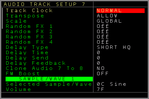
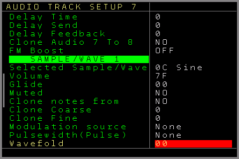
For all following values, see the Sample / Wave / Synthesis part of the manual for details and a description of their usage.
- Delay Type → Sets the type of the audio delay for the track.
- Delay Time → Sets the amount/time of the delay buffer
- Delay Send → Sets the input amplitude for the delay
- Delay Feedback → Sets the amount of the delay feedback
- Clone Audio 7 to 8 → Clones and overwrites the audio stream of Track 7 into Track 8. The audio stream is grabbed and included before the delay in the audio chain.
- FM boost → Global setting for the FM intensity
Sample Wave setting for the parts 1,2,3,4: (values can be edited here)
- Selected Sample/Wave → The currently selected sample/waveform
- Volume → Volume/Amplitude of the Sample/Wave
- Glide → Glide settings for the sample/wave part
- Muted → Sets whether the audio output of this part should be muted or not (signal can still be used for modulations)
Clone Notes from → Selects whether the notes should be cloned from the source. With this, multiple waves/samples can be sequenced from one source
Clone Coarse → If notes are cloned, this sets the note transpose/offset in semitones
Clone Fine → If notes are cloned, this sets the fine-tune for the main note.
Modulation Source → Selects whether the current audio should be either FM modulated by one or more other waves/samples or Hardsynced to another waveform
Pulsewidth (Pulse) → This determines the pulse width of the pulse wave in case the current waveform is set to ‘Pulse’
Wavefold → Sets the current wavefolding amount for the current sample/wave part
Bitcrush → Sets the bitcrush settings for the current sample/wave part
Distortion → Sets the distortion settings for the current sample/wave part
You can use the UP / DOWN buttons to switch between all 4 Wave/Sample settings (for both audio tracks).
Midi track
Pattern Screen
If a track is assigned to Midi, the Midi pattern screen is used. You can assign a track to be used for Midi in the Track Assign Screen.
A Midi track can sequence any external Midi synth/module etc. in a polyphonic manner. To sequence Midi, one of the Midi Expanders is required.
The Midi screen is split into different pages. Move the cursor further to the right to get to the next pages.
- Note 1
- Velocity 1
- Note 2
- Velocity 2
- Note 3
- Velocity 3
- Note 4
- Velocity 4
- Pattern number
- Screen name
- Track type
- Track number
- Table running on this track
- MIDI channel on each output
- Status text: what the field under the cursor does
- Row numbers
00–3F(16 visible at a time) - Note off
[ ], with release velocity
First, the sequencer column indicates the 16 visible rows.
- 4 Note columns, each with a Note value and a Velocity value. If an override channel is turned on for a column, you can see the channel assignment at the top next to the music note.
The notes range from C-0 to C-A. Beyond note C-A there are 16 random range settings RN0 → RNF which can be used to generate a random note within the selected range. Pressing the OK Button on these will bring you to the Random Ranges Screen. Random notes also work with the chord function.
The Velocity column (mostly volume) can have velocity values from 00 (Note off) to 7F (0-127). The Velocity column also contains some additional functions to generate slides (for many monophonic midi synthesizers) or to sequence the local CV/Gate outputs instead. If you press SHIFT+OK in the Velocity column (with a corresponding note) it will toggle between the additional/alternative functions.Here is an overview of the functions (together with the Note or Note off):
Local (track) CV Output functions:
A → Does only a note change on the CV output. No gate change if a note is filled in. Gate off if a note off is filled in.
A0 → Does a note change while turning the Gate OFF
A1 → Does a note change while turning the Gate ON
A2 → Does a note change while doing a trigger of 10ms (like trigger 20)
A8 → Does a note change while doing a trigger of 40ms (like trigger 80)
AT → Does a note change while toggling the current Gate state
Local (track) MOD Output functions:
B → Does only a note change on the MOD output. No gate change if a note is filled in. Gate off if a note off is filled in.
B0 → Does a note change while turning the Gate OFF
B1 → Does a note change while turning the Gate ON
B2 → Does a note change while doing a trigger of 10ms (like trigger 20)
B8 → Does a note change while doing a trigger of 40ms (like trigger 80)
BT → Does a note change while toggling the current Gate state
Local (track) Trigger/Gate functions:
T → Gate On if a note is filled in but note is ignored. Gate off if Note off is filled in, but note change is ignored.
T0 → Gate OFF without note change.
T1 → Gate ON without note change.
T2 → Trigger of 10ms (like trigger 20) without note change.
T8 → Trigger of 40ms (like trigger 80) without note change.
TT → Toggling the current Gate state without note change.
Local CV/MOD functions, regardless of current track:
C1 → Note change on CV 1 Output (no Gate change)
C2 → Note change on CV 2 Output (no Gate change)
C3 → Note change on CV 3 Output (no Gate change)
C4 → Note change on CV 4 Output (no Gate change)
C5 → Note change on CV 5 Output (no Gate change)
C6 → Note change on CV 6 Output (no Gate change)
M1 → Note change on MOD 1 Output (no Gate change)
M2 → Note change on MOD 2 Output (no Gate change)
M3 → Note change on MOD 3 Output (no Gate change)
M4 → Note change on MOD 4 Output (no Gate change)
M5 → Note change on MOD 5 Output (no Gate change)
M6 → Note change on MOD 6 Output (no Gate change)
Random Velocity Functions (for Midi notes)
R0 to RF → Use a random velocity within the selected random range. Pressing the OK button will bring you to the Random Ranges Screen.
VA to VP → Use velocity values from the Variables Variable Screen
Slide functions (for Midi notes) for Monophonic synthesizers which support a slide/glide/tie function which means that the new note is played first and then the old one is stopped. This differs from the regular flow, where the last note is always stopped before the new note plays.
S1 to S9 → Midi Slide to the new Note with Velocity 10% (S1) to 90% (S9)
S0 → Midi slide with a velocity of 100% (equal to 7F/127).
SA to SH → Midi slide with a random velocity defined by Random Range 0-7
Page 2
- Program change
- Effect 1
- Effect 2
- Pattern number
- Track number
- MIDI channel on each output
- Status text: what the field under the cursor does
- Row numbers
00–3F(16 visible at a time)
First, the sequencer column indicates the 16 visible rows.
Depending on the Midi gear used, settings might act like knobs.
- PC → Program Change. Sends a program change command to the midi channel. If the ‘On Change’ setting in the Midi track setup is enabled, it will only be sent when the value changes. Some Midi devices take a long time to recall the new program and may stop playing in the meantime. Sending only on change minimises disruption from Midi gear. You can press the OK button to directly send the program change / prelisten.
- FX1..2 → 2 FX columns with the following functions:
- PBND → Pitch bend. Sets the pitch bend, where 2000 is the middle value (i.e. pitch bend not used), 3FFF is maximum (pitch bend wheel fully up) and 0000 is minimum (pitch bend wheel fully down).
- CTL1..CTL8 → Midi Control preset messages for CC and Program change. Sends controller changes to the controllers which are set up in the midi track settings. The last 2 digits 00XX are for the value (7F maximum). If the first digit X000 is set to one, the 2nd digit 0X00 sets the Midi channel. This makes it possible to send CC values to channels other than the one set up for the track. Some devices receive main data on one channel and other parameters via CC on other channels. If the first digit X000 is reset to 0, the Midi channel set up for the track is used.
Additionally, the Control Preset can be set to Program Change in the setup screen. The meaning of the digits is the same as with the control changes but it will produce program change messages.
- CC A..CC H → Freely assignable Midi CC. While the Midi controller numbers for CC#1..8 are fixed and must be set up in the track settings, these controllers can be freely assigned.
The first 2 digits XX00 set the controller type/number and the last two digits the value.
The main difference from the first 8 controllers is that the first 8 can also be used for the Automators and other channels while the controllers 9..16 can freely be assigned in the sequence.
- CATC → Channel Aftertouch. Sends aftertouch values valid for the whole channel (supported by most Midi implementations).
- PAT1..4 → Polyphonic Aftertouch. Sends aftertouch values per note, where 1..4 is the note column which should be addressed. The values are valid from 00 to 7F.
Polyphonic aftertouch is often not implemented as it generates much more Midi traffic.
- NRP1..4 → Sets NRPN controllers. These act mostly like higher resolution CC if implemented by the midi device. The NRPN controller number is set in the Midi track setup screen, and the value can range from 0000 to 3FFF. Be aware that an NRPN message sends up to 4 times as much Midi data compared to a normal CC message. So handle with care to avoid a midi traffic jam (especially in combination with Automators).
- SNRP → Sets the controller type of NRPN4. With this, NRPN4 can be used as a flexible controller. The controller type number can be up to 3FFF.
–PCRD → Plays a chord within the Midi columns. Depending on the selected chord there are 2 to 4 notes. The first note in the Midi note columns defines the base note of the chord. In the Midi note columns you can see how many notes are used for the chord, and the notes are then played on these columns. Please be aware that a chord of multiple notes also needs multiple note-off commands. These can either be inserted via the regular note-off commands or by using the same chord with a note-off in the first note column.
Available chords for Midi are: Minor 2nd, Major 2nd, Minor 3rd, Major 3rd, Perfect 4th,
Diminished 5th/Tritone, Perfect 5th, Minor 6th, Major 6th, Minor 7th, Major 7th, Triad Major, Triad Minor, Triad Diminished, Triad Diminished 5th, Triad Diminished Augmented, Triad Suspended 4th, Triad Suspended 2nd, 7th Dominant, 7th Minor, 7th Major, 7th Minor Major, 7th Suspended, 7th Augmented, 7th Augmented Major, 7th Augmented 9th, 7th Half Diminished, 7th Diminished, 7th Diminished 5th, 7th Diminished Flat 9th, 6th, 6th Minor, 9th, 9th Minor, 9th Major, 9th Diminished 5th, 11th.
- +*-/ → Add, Multiply, Subtract, Divide last FX. Same as the function in a modular track.
- VELO → Velocity override. This command can either override the velocity value of one of the Midi note columns or add to/subtract from the last known velocity when used in a table. Using this command in a table can create nice Midi Delay or Fading effects. The first digit defines which columns should be affected and the 2nd digit sets the functionality: Overrule, Subtract, add. The last 2 digits define either the overrule velocity value or the subtract/add amount.
All further parameters are exactly the same as for a Modular CV/Gate Track, so all functions of the local tracks can still be used, with the following exceptions:
- KILL → Kills the note (sends a note off) after a set time. The first digit X000 selects the note column which should be killed (0 is for all notes and 1..4 for notes 1..4), and the last three digits 0XXX set the time until the note stops. Small amounts can generate very short note times (shorter than steps).
Page 3
- Effect 3
- Patch
- Table
- Groove
- Pattern number
- Track number
- MIDI channel on each output
- Status text: what the field under the cursor does
- Row numbers
00–3F(16 visible at a time)
First, the sequencer column indicates the 16 visible rows.
- FX3 → Same FX as on page 2.
- Patch → Column to set a patch. The function is the same as with the local CV/Gate tracks. OK creates a new patch on an empty spot. SHIFT+OK clones a patch. Greyed-out patch numbers are either empty or already used by other track types. OK on a patch number will enter the Patch Screen
- Table → Set a table. You can create a new table by pressing the OK button. By pressing SHIFT+OK on a current table you can clone the currently selected table into a new table. Selecting ** here (the highest value) is the ‘stop table’ command.
- Groove → Apply groove settings just as for the other tracks (see the CV/Gate Pattern screen for a description).
Specials for the Midi tracks:
A track can be assigned to a channel (multiple tracks can use the same channel, but be careful with overlapping notes). On top of that, CC values 1..8 can also be sent to other channels.
A setting (in the Midi track settings) allows the notes of the first note column to be sent via Midi and also to the local CV/Gate outputs, where a note on sets the gate and a note off resets it.
Pressing the OK button on the Note Columns will pre-listen all notes in the row. Navigating UP/DOWN plays the notes while navigating.
The general playback of a Midi pattern row uses the following order:
Patch > Program Change > FX1 > FX2 > FX3 > Midi Notes 1,2,3,4 > Aftertouch
So, for example, parameters changed in FX1 already affect FX2, and so on.
The probability settings can be applied to the Note columns 1..4, the FX columns 1..3 and the whole row.
Track Setup (Midi Track)
- Track Clock → See Track Setup Screen.
- Transpose → Allows or prevents transposing of the track. This applies to both the global and the track transpose.
- Scale → See Track Setup Screen.
- Loc.Trigger Delay → See Track Setup Screen.
- Random FX1..3 → Enables randomized values for the selected FX. When turned on with a range selected, all FX values in that column will play with random values within the selected ranges. This can also be enabled/disabled with the Random FX command (RDMN) from the FX list. Press OK to get to the Random Ranges Screen and change the ranges.
- Base Midi Channel → Set the Midi track to a midi channel so the generated Midi data from that track is routed to that channel. (unless overridden otherwise). Midi Channels 1-16 can be selected for the regular Midi-IO and TRS-A Expanders. Midi Channels 1-16 for TRS, USB-Host and USB-Device can be selected with the Multi-IO Expander.
- Overrule Column 2,3,4 → Usually all notes from the 4 midi note columns will be played on the base midi channel. This can be overridden so the selected columns can sequence on another channel.
- Note Offset → Main transpose/offset for Midi notes. This is used to match different Midi devices. The offset is added to the main transpose and can be either positive or negative.
- Record Columns → Select the number of Midi voices that can be recorded in a Midi Track.
The first 4 settings (1, 1+2, 1+2+3, 1+2+3+4) select how many columns are used for midi recording (which also defines the recording polyphony).
The latter settings (2, 3, 4) define that the recording should be monophonic into the selected column only.
Record Columns: 1 to 1+2+3+4 record polyphonically, 2, 3 and 4 record monophonically into that column only.
So if, for example, the setting is 1+2, only the first 2 columns are available for Midi recording and the other 2 columns stay untouched.
- Clone to Modular → If enabled, the Midi notes and note offs from the first note column are also sent/cloned to the local CV and gate outputs of the track. Note on sets the gate and the CV value to the note, and note off (also with KILL) resets the gate again. The Velocity value will be output onto the MOD output of the track.
- Program Change → If set to ALWAYS then all program change events are sent. If set to ON CHANGE then it is only sent if the program number changes. Some Midi devices need quite some time until the program/patch is completely recalled and might stop responding for a while. This setting minimizes any possible problems/glitches.
If it is set to ALWAYS PRE it will always be sent, and also in advance (5 steps earlier if possible) if the program change of the next playing pattern is placed in the first row (pre fetch). Please note that if you initiate a pattern change after these steps, the program change will already have been sent. This is a convenient feature for Elektron (and possibly other) gear which needs the program change one bar in advance to be able to react in time.
– Automation Limit → Limits the amount of data generated by the Automator and sent to the Midi destinations Pitch bend, CC and NRPN. The settings are 100%, 50%, 25%, 10% and 5%. Keep the settings as low as acceptable to minimize Midi data overflows. - Control Preset 1..8 → Sets the Controller (CC) number for the first 8 CC FX values or selects this Control Preset to be used for additional Program Change messages. These can be used with different Midi channels for CCs and also as Automator destinations.
- NRPN 1..4 → Sets the NRPN-Controller (CC) number for the 4 NRPN FX values. These can then be accessed from the FX columns and also used as Automator destinations.
Trigger16 Track
Pattern Screen
This pattern screen is only available with a connected ‘Trigger16’ expander. You must assign a track to be used together with the expander in the Track Assign Screen.
As the pattern values don’t fit on one screen, it is split into 3 pages.
Page 1
- Trigger columns
T1–T8 - Trigger set in the drum matrix (yellow)
- Pattern number
- Screen name
- Track type
- Track number
- Table running on this track
- Status text: what the field under the cursor does
- Row numbers
00–3F(16 visible at a time) - Trigger function, here
20
First, the sequencer column indicates the 16 visible rows.
Then the following columns:
- TR1 .. TR8 are the columns for the first 8 trigger outputs. The values are exactly the same as on the local Trigger columns. (see the Modular Track Pattern screen for an explanation).
As a side note, these can also be the columns TR9 .. TR16. You can set the track to use the 2nd half of the 16 outputs in the track settings.
The trigger part is highlighted if a trigger is set up in the drum matrix for the same trigger position.
Page 2
- Effect 1
- Effect 2
- Effect 3
- Pattern number
- Track type
- Track number
- Table running on this track
- Status text: what the field under the cursor does
- Row numbers
00–3F(16 visible at a time)
First, the sequencer column indicates the 16 visible rows.
- FX1 .. FX3 → FX columns dedicated to the Trigger16 expander with the following parameters:
- TR1 .. TR16 → Trigger values, same as the regular trigger values
- TRBL → Trigger Binary Value Low. Sets the binary value for the first 8 Trigger outputs. The triggers are set or reset depending on the value. This could be used for some cool dividers.
- TRBH → Trigger Binary Value High. Sets the binary value for the second 8 Trigger outputs (9..16). The triggers are set or reset depending on the value.
- TREF → Trigger extra effects. Some additional trigger functions:
All Triggers/Gates Off → turns all Trigger/Gate outputs off.
Swap Outputs → Off/On. If on, the 8 trigger columns are swapped to triggers 9..16 (same as the track setup setting, but from the sequence).
Toggle Swap Outputs → Toggles the columns between being 1..8 or 9..16
- NOTE → Plays or changes the note on the local CV+Gate output. If the first digit is 0, only a note change will be sent to the CV output. If the first digit is 1, a trigger (set up in the track setup → Matrix Trigger) is also sent together with the note. The filled in notes can currently be seen in the status bar. (subject to change).
- All further parameters are exactly the same as for a Modular CV/Gate track, so all functions of the local tracks can still be used. The only difference is the probability settings, which now belong to several trigger outputs and FX.
PR12 belongs to the columns 1+2 (Trigger outputs 1+2 or 9+10)
PR34 belongs to the columns 3+4 (Trigger outputs 3+4 or 11+12)PR56 belongs to the columns 5+6 (Trigger outputs 5+6 or 13+14)
PR78 belongs to the columns 7+8 (Trigger outputs 7+8 or 15+16)
The outputs for the columns are determined by the Swap Outputs function.Additionally, the same outputs on the drum-matrix are affected.
Page 3
- Patch
- Drum matrix, triggers 1–16
- Groove
- Pattern number
- Track type
- Track number
- Table running on this track
- Status text: what the field under the cursor does
- Row numbers
00–3F(16 visible at a time)
First, the sequencer column indicates the 16 visible rows.
- Patch → Set patches for all FX parameters. Same usage as the Patch column in a CV/Gate track.
- DrumMatrix → 16 columns for the 16 outputs. The drummatrix is a special classic view where you can set and reset triggers in a matrix for all Trigger16 outputs as well as the local trigger outputs.
- Groove → Groove settings as known from the other tracks (see the CV/Gate pattern screen for further explanation).
Special DrumMatrix usage:
The triggers in the drum-matrix can be enabled with SHIFT+CURSOR RIGHT and disabled with SHIFT+CURSOR LEFT or via SHIFT+DELETE. Multiple rows or columns can be deleted using the mark/delete functions.
The kind of triggers as well as the output per column can be changed in the track settings screen.
Complete and partially selected drum-matrix content can be copied and pasted like other pattern content, also between Trigger16 and Multifunctional/I2C tracks.
Values filled in on Page 1 or Page 2 override any drum-matrix trigger on the same trigger output. For example, if Trigger 3 is enabled in the drum-matrix with the drum-matrix triggers set to 20, and on Page 1 Trigger 3 is set to 52 in the same row, then the 52 overrides the 20. This rule is defined per ‘matching’ output, not per column.
The Triggers can also be muted or soloed. To mute a Trigger your cursor must be on either a trigger column in the first page or on the drum-matrix. Pressing SHIFT+DOWN+START will mute/unmute the trigger. Pressing SHIFT+UP+START will Solo or unsolo the Trigger. When unsoloing, all triggers will be unmuted as well. The function works the same as muting and solo-ing for the regular tracks.
SHIFT+OK and releasing the buttons toggles between the default trigger value, FE, 00 and ‘–’.
Drum-Matrix patterns can be moved per trigger. Using SHIFT+OK+CURSOR DOWN moves the currently selected trigger column in the drum-matrix one step down. Triggers that shift out of the last row will be inserted in the first row. Using SHIFT+OK+CURSOR UP moves the currently selected trigger column in the drum-matrix one step up. Triggers that shift out of the first row will be inserted in the last row.
Besides setting different trigger points in the drum-matrix manually, a different input mode is available. Drum triggers can be inserted in a ‘Euclidean Rhythm’ style. The idea is to add a number of trigger points with the pauses between them as equal as possible. For example, if a pattern has 64 steps and 16 triggers should be filled in, then a trigger will be inserted every 4 steps.
So it is possible to insert 0 to 64 triggers, and the trigger points and pauses are automatically calculated and inserted in the selected trigger column of the drum-matrix.
By using SHIFT+OK+LEFT, the number of triggers is decreased and the euclidean rhythm is inserted. By using SHIFT+OK+RIGHT, the number of triggers is increased and the euclidean rhythm is inserted. Note that the counting starts at the cursor position, so if, for example, the cursor is on the 7th row, then the euclidean counting starts from the 7th row to the last row and wraps around and continues on rows 0..6. The euclidean function will also consider the selected pattern length in its calculations.
It is also important to know that currently inserted trigger points of the trigger column will be overwritten by the euclidean input. On the other hand, columns that were inserted in the euclidean way can be edited further to get different results.
Pressing OK on a selected Trigger (Trigger columns or drum-matrix) will pre-listen that trigger. SHIFT+DOWN+OK on the 8 trigger columns will pre-listen the whole trigger row.
Using the move and euclidean functions on the drum matrix is a fast way to create interesting drum rhythms on the fly.
If the Trigger16 Track is set to Piano Roll mode, each drum trigger column represents a note which depends on the base note chosen in the track setup. So if the base note is set to C-2, the leftmost trigger column is C-2, next to it C#2, D-2 and so on. At the top of the pattern view you can see the sharp and flat notes coloured, based on the base note. A filled-in trigger plays the note on the local CV track and fires a trigger on the local trigger output. The trigger settings are the same that are used for the Drum-Matrix. Note that the drum-matrix triggers also fire. If you want to prevent the drum-matrix from firing in piano roll mode, scroll past the highest base note (B-8): there you can choose all base notes again, but with the additional drum-matrix output turned off.
The general playback of a Trigger16 pattern row uses the following order:
Patch > FX1 > FX2 > FX3 > Trigger Columns 1-8 > Drummatrix 1-16
So, for example, parameters changed in FX1 already affect FX2, and so on.
Track Setup (Trigger16 Track)
A ‘Trigger16’ expander is needed to enter this screen.
- Track Clock → See Track Setup Screen.
- Transpose → Allows or prevents transposing of the track. This applies to both the global and the track transpose.
- Scale → See Track Setup Screen.
- Loc.Trigger Delay → See Track Setup Screen.
- Random FX1..3 → Enables randomized values for the selected FX. When turned on with a range selected, all FX values in that column will play with random values within the selected ranges. This can also be enabled/disabled with the Random FX command (RDMN) from the FX list. Press OK to get to the Random Ranges Screen and change the ranges.
- Swap Outputs → Swaps the first row 1..8 of the trigger expander outputs with the second row 9..16. This is implemented because of the limited number of columns in a track, so you can decide which outputs to access directly. Expanders can be assigned to multiple tracks, for example the first 8 triggers on one track and the last 8 triggers on another track. Besides that, the other outputs are always available through the FX column and can be triggered on the Drum-Matrix.
- Matrix X Destination 1..16 → Sets the trigger destination for the selected column. The destination per column can be either one of the Trigger16 outputs or one of the 6 Local Trigger outputs. The same output can be used on multiple columns.
- Matrix X Type 1..16 → Sets the trigger type per column for the drum-matrix. Here all trigger types (same as regular trigger types) can be filled in, and the drum matrix triggers then use these settings.
- PR → Piano Roll function. Enables a (vertical) monophonic piano roll function. If turned on, you can set a base note, or a base note without a trigger. All triggers entered in the Drum-Matrix will then also play a note on the local CV/Gate track, beginning with the base note on the first trigger and then semitones up until the last trigger. The Notes can be played with either the local track trigger or not (in the setting after the highest base note). In Piano Roll mode, the ‘black’ and ‘white’ piano keys are marked at the top of the 16 matrix triggers.
- Firmware Update → Enters the Expander Firmware Update Screen. NSA-Expanders are smart devices and can get firmware updates for new functions or bugfixes as well. (See NSA Firmware update screen)
- Test Trigger 1..16 → Here the Trigger/Gate outputs can be tested (0 Volt = Off, 5 Volt = On). The LED should also be on or off according to the voltage.
CV 16 Track
The CV16 expander adds 16 additional CV outputs to the NerdSEQ which can be used as additional note, pitch or modulation outputs. To control the additional outputs, a dedicated pattern screen and setup are available. Also, one expander can be assigned to multiple tracks so each track uses its own dedicated outputs.
Several columns and the FX in a pattern can play notes or change pitches. The Automators and Mappings can also manipulate the CV16 outputs/functions.
In addition to the notes the following effects/modulators can be applied for each CV16 output:
Glide:
For each CV output there are glide settings. These work just like the glide setting on the Modular tracks of the NerdSEQ itself with the 2 parameters speed and resolution.
The speed decides how fast the glide is and the resolution defines the quantisation of each speed iteration. To get snappy glides from one note to the next, increase the resolution a bit and keep the speed at a low value. The glide is per CV output, and a pitch/note glides to the new note with the assigned speed/resolution. The glide settings can be changed in the track setup or from the FX columns.
Modulators:
There are 16 modulators in total: 8 Envelopes and 8 LFOs. Each can be used on all outputs of the CV16 expander. So you can assign every Envelope to every output of the CV16 expander. The same applies to the LFOs.
For example, you can assign Envelope 2 to CV outputs 1 and 4, Envelope 4 to CV14, LFO 2 to CV2 and CV7, and so on… You could even assign one Envelope to 15 or all 16 outputs and start them all at different times. Keep in mind that only 1 modulator can be active per CV output, so an Envelope and an LFO on the same CV output is not possible. The most recently started modulator will stop the previous one.
Each modulator has dedicated functions and settings (each 8 times) which are:
Envelope → Since these are ASR envelopes, each envelope has Attack, Sustain and Release settings.
Every Envelope can be set/started into different stages:
Attack → Release → ‘Fires’ the envelope, going through its attack phase and when it reaches the sustain voltage level, the Release phase starts.
Attack → Sustain → ‘Fires’ the envelope, going through its attack phase, and when it reaches the sustain voltage level it holds that level until the release phase is started.
Release → Starts the release phase from the current sustain level.
Loop → ‘Fires’ the envelope, going through its attack phase; when the sustain voltage is reached, it goes directly into the release phase and loops this endlessly.
The Attack/Release times go from 20 milliseconds to ~14 minutes. The Sustain voltage can be set up from 0 to 10 Volts in 255 steps.
LFO:
Each of the 8 LFOs has 3 settings: Waveform, Speed and Amplitude.
The possible waveforms are: Sine, Triangle, Sawtooth, Ramp, Square, Noise and Random.
The random waveform is special as it contains all waveforms except for noise and it changes between them randomly at a random moment. So it can switch from triangle to ramp and then to sine and so on at various times. The speed changes the wave iterations between 0.0011 Hz (~14min) and 21.8 Hz. The amplitude ranges from 0 to 10 Volt (-5/+5 bipolar) in 255 steps, with a finer resolution in the smaller ranges.
The LFOs can be started and will run endlessly. There is also a command which resets the LFO, so the waveform starts over.
For each CV output there is an additional setting to decide whether the modulator (Envelope or LFO) should be pure or added to the current Note/Pitch.
If the setting is pure, the following rules are valid for the modulators:
Envelope
The ASR (Attack Sustain Release) envelope starts its attack phase at 0 Volt (-5V) and rises until it reaches the sustain voltage. At full sustain (255/FF) this is 10 Volt (5V). If the release phase is finished the voltage is 0 Volt again.
LFO
The LFO midpoint with the pure setting on the CV output is 5 Volt (0V). So the LFO will swing between 0 and 10 Volt (-5/+5V) at full amplitude.
If the CV output is set to ADD, the modulator voltage is added to the current pitch or note value. The Modulators will act as bipolar modulators. In this case the following rules apply, assuming, for example, the note C-2 → 2 Volt (-3V):
ADD for the Envelope
The attack phase starts from 0 Volt (-5V), because it cannot go lower than the lowest possible voltage. It rises to the sustain level (if sustain is set to full) of 7 Volt (2V) and returns to the lowest value after the release. Note C-5 would output the full range of the envelope, and higher notes would shift the offset higher.
ADD for the LFO
The LFO swings bipolar around the note/pitch value. Depending on the amplitude setting, the bipolar LFO swing has values from plus/minus 5 Volt to millivolts around the current pitch value.
Once a modulator is started it will stay active until it is stopped by the sequence or the user.
For CV outputs which are set to pure, note values have no effect.
A modulator can be stopped with the appropriate command in the pattern screen for the CV output or in the pattern Nerd Menu → Stop all sound. If modulators are stopped, the original Note/pitch value/voltage will return to the CV output.
Besides the sequencing, the CV expander can also be a destination for live recording or playing through the CV inputs or Midi. Currently, 1 CV note can be recorded from the CV inputs together with an envelope (using the settings of Envelope #8). On a Gate On at the CV inputs, an envelope with the Attack→Sustain phase is entered into the CV16 columns together with the note. On a Gate Off, the release phase is entered.
If the recorded input is a Midi signal, flexible settings are available to achieve polyphonic recording.
The input settings can be from 1 up to 6 polyphonic CV notes, or 1 to 5 CV notes plus the envelope. All these are filled into the CV16 columns. If the envelope function is activated, Envelope #8 is used as well. When multiple keys are pressed, the envelope will run through Attack→Sustain on the first note and starts the release phase when releasing the last note.
Another setting is the 2×2 or 3×3 polyphonic recording. In this mode a 2 or 3 voice polyphonic recording and envelope generation is possible. In 2×2 mode, up to 2 notes at the same time will be entered in the first 2 columns, while the next 2 columns set the envelopes for these notes. So the envelope in column 3 is for note 1 in column 1, and the envelope in column 4 is for note 2 in column 2. If 3×3 mode is active, it records up to 3 notes, each with an envelope, where the first 3 columns are the notes and the next 3 columns the envelopes for the corresponding notes. This allows full 3-voice polyphony per track.
Please keep in mind that the Glide, Envelopes and LFO can never fully replace real analogue slews, envelopes or LFOs. But they are definitely a very good addition for many applications.
Pattern Screen
This pattern screen is only available with a connected ‘More CV 16’ expander. You must assign a track to be used together with the expander in the Track Assign Screen
As the pattern values don’t fit on one screen, it is split into 3 pages.
The CV16 or ‘More CV16’ Expander adds some more flexible screens and functions which need some additional explanation compared to the regular screens.
To get as many functions as possible within the given columns and user interface, multiple functions can be assigned from the same column in the first 6 columns. Also, each column can be assigned to a different destination. The destinations can be set in the CV16 Setup Screen.
Destinations for the first 6 columns can be one of the CV16 outputs (1..16), the local CV/MOD outputs of the track (TCV or TM), CV1 to CV6 (LC1..LC6) or MOD1..6 (LM1..LM6). So all CV/MOD outputs can also be controlled with notes and pitches from within the 6 CV16 columns. Even the Triggers/Gates can be manipulated from here as well with a limited set of available Gates/Triggers (Gate On/Off/Toggle, Trigger 20ms and 40ms).
Besides the destinations of the CV setup, different CV types can be used in all of the 6 columns. If the tracks are set up to use one of the CV16 outputs, then the following features can be used:
Notes, Pitch, Trigger/Gate, Envelopes (Attack/Sustain/Release), LFO (Sine, Triangle, Sawtooth, Ramp, Square, Noise, Random, Triggers on the CV16 output (from CV16 firmware V1.2 and higher)).
- Six CV columns
- Raw CV value (above 120 it is no longer a note)
- Pattern number
- Track number
- Screen name
- Track type
- Table running on this track
- Glide and modulator settings of the column under the cursor
- Status: where this column goes (CV16 output)
- Row numbers
00–3F(16 visible at a time) - Value shown as a note
Page 1
Columns 1..6:
If regular notes are filled in, the assigned outputs will change the voltage to the note value (if no modulator is running on that output). Depending on the offset switch, the voltage for note C-0 is either 0 Volt or -5 Volt. After the highest note C-A (as in, scroll the note-value further than note C-A) the modulators can be set up. To fit everything into the columns, a special number format is used: of the 2 digits, the left digit defines the modulator number.
The right digit defines the modulator type. The following types are available:
0 → Envelope Attack > Release (column also marked with a ‘^’ )
1 → Envelope Attack > Sustain (column also marked with a ‘^’ )
2 → Envelope Release (column also marked with a ‘^’ )
3 → Envelope Loop (column also marked with a ‘^’ )
4 → LFO Start/Continue (column also marked with a ‘~’ )
5 → LFO / Envelope Reset (column also marked with a ‘<’ )
6 → Stop Modulators (column also marked with a ‘-’ )
Here are some examples of the values:
Filled into the first column, which is assigned to CV2:
^10 → Envelope 1 start as Attack/Release on output CV2
^11 → Envelope 1 start as Attack/Sustain on output CV2
^12 → Envelope 1 starting release phase on output CV2
^13 → Envelope 1 set to loop (repeating attack/release) on output CV2
~14 → Start/continue LFO1 on output CV2
~34 → Start/continue LFO3 on output CV2
<55 → Reset LFO5 on output CV2
Note that, for example, Envelope 2 is a different modulator from LFO2. The numbers just decide which function you want to start on which column/CV output.
The same LFO or Envelope can run on multiple CV outputs, even in different stages.
Another example for a column which is assigned to CV12:
~24 → Start/continue LFO2 on output CV12.
-16 → Stop modulator on output CV12. The modulator number is not relevant here. The column / CV output is released from the running modulator and returns to its original note/pitch.
Envelope stages continue from the current ‘voltage’, so if a release phase was not finished and the envelope is started again, it will continue with the attack phase from the current release level. Use the reset command to completely reset and restart an envelope.
With CV16 Firmware V1.2 or higher the CV16 outputs can also generate simple triggers. For this, the one-shot LFO curve TRIG is implemented. This will generate a Trigger with a dedicated amplitude and length (speed setting) on the CV16 output. A speed setting of 00 will reset the Trigger/Gate and a speed setting of FF will set the Gate to the specified amplitude.
Furthermore, above the modulator numbers a set of Triggers/Gates can be set.
So if you scroll beyond the modulators the following options are available:
The first set is for the trigger/gate output of the current track:
TT0 → Gate Off for the local Trigger/Gate output of the track.
TT1 → Gate On for the local Trigger/Gate output of the track.
TTT → Toggle Gate for the local Trigger/Gate output of the track.
TT2 → Trigger of 10ms for the local Trigger/Gate output of the track.
TT8 → Trigger of 40ms for the local Trigger/Gate output of the track.
The 2nd set is for the destination of the column. If the column is assigned to CV 1..6, the destinations are the local trigger/gate outputs 1..6. If they are set up for the local track 1..6, then these are also automatically assigned to 1..6. All other assignments use the current track.
Assuming the column uses CV3 as its destination:
TD0 → Gate Off for the Trigger/Gate output 3.
TD1 → Gate On for the Trigger/Gate output 3.
TDT → Toggle Gate for the Trigger/Gate output 3.
TD2 → Trigger of 10ms for the Trigger/Gate output 3.
TD8 → Trigger of 40ms for the Trigger/Gate output 3.
Next are 2 sets to generate randomness.
First there is RN0 to RN7 which generates a note within the selected range 0-7.
Then there is R 0 to R 7 which generates a pitch within the selected range 0-7.
Pressing the OK button on the random commands will bring you to the Random Ranges Screen.
Lastly, there are the pitch settings of the assigned outputs.
These operate like the normal pitches from 000 to FFF which represent 0 to 10 Volt (-5/+5).
As a side note, the pitch values are scaled, so not all 4095 (FFF) values are available. In fact, only 3892 different values are available, with some numbers skipped across the whole range. In general use you will not notice this at all, as the voltage steps are so fine that skipping one value is not audible. If you really need them anyway, you still have the full range with 4095 values available through the FX columns.
It is also possible to use the Trigger16 expander from within a CV16 track. To do so, set one or more Trigger16 outputs of a Trigger16 expander as column destinations in the Track Setup.
Instead of the pitch commands, the values 00 – FE can then be used to control the Trigger16 expander output with its usual trigger commands. Additionally, the Trigger Destination commands TD0, TD1, TDT, TD2 and TD8 in the same column can be used to control the Trigger16 outputs.
As a fast browsing option, you can also use SHIFT+OK to directly jump between Notes, Modulators, Triggers, Pitches and an empty value.
On the right side of the screen you will find the current settings of the selected column. These can differ depending on which kind of destination is selected for the column, but also on which type the cursor is currently on.
These are not only visible but can also be edited directly. By pressing the PATCH button your cursor toggles from the left column side to the right side. The settings can then be edited as usual using SHIFT+UP/DOWN/LEFT/RIGHT.
If the destination is a CV output of the expander, you have the following settings:
GLC → Glide Speed
GLR → Glide Resolution
MOD → Modulation pure or added
If you selected a modulator, you get the additional settings of the modulator. For an envelope these are:
ATK → Attack value of the selected envelope
RLS → Release value of the selected envelope
SUS → Sustain value of the selected envelope
For an LFO these are:
TYP → The type of the selected LFO (e.g. Sine, Sawtooth etc.)
SPD → The speed of the selected LFO
AMP → The amplitude of the selected LFO
Pressing PATCH again will bring you back to the regular column editing.
At the top of the screen you can see whether, and what kind of, modulations are active on that output.
A ‘^’ means an active envelope. A ‘~’ means an active LFO. If the modulation is set to pure, no note will be played on that output/column until the modulation (Envelope or LFO) is stopped and the output is released again for any other function such as Notes. There is one exception for this behaviour. If the setting ‘Pure Overrule’ is enabled, a new note will disable the modulation. Also, SHIFT+STOP on a stopped sequencer will disable any CV16 modulations.
On the right bottom side you see a graphical representation of the currently selected modulator (if the cursor is on it).
While editing, press OK to pre-listen the current sequencer row.
Page 2
- Effect 1
- Effect 2
- Pattern number
- Track number
- Status text: what the field under the cursor does
- Row numbers
00–3F(16 visible at a time)
On the second page there are 2 FX columns. These mostly use a special coding for the 4 digits, which is explained for each function. For all CV16 functions, details/help is available in the statusbar, so you should be able to work with all of them without checking the manual again.
The following FX functions are available:
CV A to CV H → Change the CV value. The leftmost digit Xxxx defines the CV output 1 to 16 and the three right side digits xXXX define the CV value/pitch from 000 to FFF.
NT A to NT H → Change the Note. The 2nd left digit xXxx defines the CV output 1 to 16 and the two right digits xxXX define the note value.
GL A to GL H → Glide settings for the 16 CV outputs. The first digit Xxxx defines the CV output. The second digit xXxx defines whether it is the Glide Speed (0) or the Glide Resolution (1) setting. The 2 digits on the right xxXX are the value of the selected settings from 00 to FF. Be aware that the current settings will be filled in automatically when starting to edit.
ST A to ST H → Start Modulator. With this you can start (or stop) any modulator on any CV output.
The 2nd digit from the left xXxx defines the CV output 1..16. The third digit from the left xxXx defines the Modulator number 1..8. And the rightmost digit xxxX defines the type of modulator.
These are: 0: Attack→Release Envelope, 1: Attack→Sustain Envelope, 2: Release Envelope, 3: Loop Envelope, 4: Start/Continue LFO, 5: Reset LFO, 6: Stop modulator
SENV → Set Envelope Parameter. Used to change envelope parameters from the playing sequencer. The first digit from the left (Xxxx) is the envelope number. The 2nd digit from the left xXxx defines which envelope parameter is affected 0: Attack, 1: Release, 2: Sustain. And the 2 digits on the right xxXX define the value. Note that the current Envelope settings are automatically filled in.
SLFO → Set LFO parameter. With this you can change the settings of one of the 8 LFOs.
The first digit from the left Xxxx is the LFO number. The second digit xXxx selects the setting to be changed: 0: Type, 1: Speed, 2: Amplitude. The last 2 digits xxXX are for the value of the setting.
SADD → Set modulation for the CV output 1..16 to pure or add setting. Here the 3rd digit from the left xxXx defines the CV output number. The last digit xxxX defines whether the modulator should be added to the current pitch (set to 1) or be pure (set to 0).
PROW → Probability for the whole row except for the last FX column.
PCRD → Play Chord. Plays a chord on multiple CV outputs. Xxxx selects the column and start CV for the base note. For example, if set to 2xxx, the 2nd column is used for the base note, and the CV assigned to this column plays the first note of the chord. The following CVs are then used for the rest of the chord. For example, imagine a chord with 4 notes is selected and the column uses CV6. The chord will then be played on CV6, CV7, CV8 and CV9. So the chord is not related to the other columns. Even more, multiple chords can be played at the same time on one step using more chord FX commands with other base-column selections.
xxXX defines the selected chord (different chords use 2 to 6 notes). The following chords are available: Minor 2nd, Major 2nd, Minor 3rd, Major 3rd, Perfect 4th, Diminished 5th/Tritone, Perfect 5th, Minor 6th, Major 6th, Minor 7th, Major 7th, Triad Major, Triad Minor, Triad Diminished, Triad Diminished 5th, Triad Diminished Augmented, Triad Suspended 4th, Triad Suspended 2nd, 7th Dominant, 7th Minor, 7th Major, 7th Minor Major, 7th Suspended, 7th Augmented, 7th Augmented Major, 7th Augmented 9th, 7th Half Diminished, 7th Diminished, 7th Diminished 5th, 7th Diminished Flat 9, 6th, 6th Minor, 9th, 9th Minor, 9th Major, 9th Diminished 5th, 11th
PH 1 to PH8 → Placeholders for future FX and currently unused.
All further parameters are exactly the same as for the Modular CV/Gate tracks, so all functions of the local tracks can still be used. The only difference is the probability settings, which now belong to several CV outputs and FX.
The Probability settings are defined as follows:
CV1, CV2, CV3, CV4, CV5+6, FX1, FX2, FX3.
- Effect 3
- Patch
- Table
- Groove
- Pattern number
- Track number
- Status text: what the field under the cursor does
- Row numbers
00–3F(16 visible at a time)
Page 3
The 3rd page contains the 3rd FX column which has the same settings as the previous 2 FX columns.
Next to it are the Patch and Table settings. The Patch function works in the same way as for the local CV/Gate tracks and so all FX parameters of a CV16 expander can be manipulated from the patches. The same applies to the Table column. With both the Patch and Table columns, you can create a new Patch/Table by pressing the OK button and clone into a new Patch/Table by pressing SHIFT+OK on a selected Patch/Table.
The last column on the right is the groove column, which works in the same way as the groove column from the normal CV/Gate tracks.
The general playback of a CV16 pattern row uses the following order:
Patch > FX1 > FX2 > FX3 > CV Columns 1-6
So, for example, parameters changed in FX1 already affect FX2, and so on.
Track Setup (CV16 Track)
A CV16 Expander is needed to enter this screen.
- Track Clock → See Track Setup Screen.
- Transpose → Allows or prevents transposing of the track. This applies to both the global and the track transpose.
- Scale → See Track Setup Screen.
- Loc.Trigger Delay → See Track Setup Screen.
- Random FX1..3 → Enables randomized values for the selected FX. When turned on with a range selected, all FX values in that column will play with random values within the selected ranges. This can also be enabled/disabled with the Random FX command (RDMN) from the FX list. Press OK to get to the Random Ranges Screen and change the ranges.
- Record Voices → Sets the number of voices which can be recorded from Midi. The following settings are currently available: 1..6 records Midi into that number of columns. So if set to 3, only the left 3 columns are used to record the Midi notes.
1..5 + ENV8 → 1 to 5 columns are used to record notes, and the envelope data is additionally filled into the next column. With a polyphonic Midi stream the rules are: when the first note is pressed, Envelope 8 is filled in as Attack/Sustain envelope on the field next to the highest possible selected note column. When the last note is released on the keyboard, a release for Envelope 8 is filled in. For example, if you set up 2 voices + envelope, then the envelopes are always filled in on the 3rd column.
Furthermore, there are the 2×2 and 3×3 record voice settings, which allow full polyphonic note + envelope generation. Here notes are filled into the first 2 or 3 columns, and the envelopes belonging to each note are filled into the following 2 or 3 columns.
If a column is set up as a Trigger16 destination, Gates/Triggers will be filled in instead of the envelopes.
Record Voices: note columns, plus the envelope (or Trigger16 gate) columns of the ENV settings. - Pure Overrule → Defines whether a modulator in Pure mode should be stopped when a note is filled in and played.
- Destination 1..6 → Defines the destination for the columns 1..6. The following destinations are available:
EXT CV1..CV16 → the CV outputs on the expander.
TRACK CV → The CV output on the NerdSEQ of the current track.
LOC CV1..CV6 → The NerdSEQ CV outputs 1..6.
TRACK MOD → The MOD output on the NerdSEQ of the current track.
LOC MOD1..6 → The NerdSEQ MOD outputs 1..6.
TRIGGER16 1..16 NSA 1..4 → Outputs 1 to 16 of a Trigger16 expander (Address/Channel 1 to 4)
- Glide 1..16 → Set the Glide Speed and Resolution for each CV output.
- Modulation 1..16 → Set the behaviour of the modulations onto the current pitch/note. In pure, only the modulators are routed to the output. In add, the modulator is added to the current pitch/note.
- Envelope 1..8 Settings → Attack, Release, Sustain. A graphical representation of the envelope shape is drawn on the screen.
- LFO 1..8 Settings → LFO Type (Sine, Triangle, Sawtooth, Ramp, Square, Noise and Random. Additionally the ‘LFO’ type ‘Trigger’ can be selected if the CV16 firmware uses version V1.2 or higher) plus the Speed and Amplitude.
- Firmware Update → Enters the NSA Firmware update screen.
CV16 Calibration
- Get Calibration → Requests the CV16 calibration settings for the selected expander. After the NerdSEQ has successfully received the relevant data from the expander, the values are presented in the fields below. With a multimeter connected to the CV outputs you can calibrate each output.
With CV16 firmware lower than V1.2 you will receive 2 settings per output. You can calibrate these using the following instructions:
Select CV 1 __ 0 V. The multimeter should now read 0 Volt. If not, change the values in the right hand field until it best matches 0 volt.Now select CV 1 __ 10V. You should now measure 10 Volt at CV output 1. If not, change the value in the right hand field until it best matches 10 volt.
Proceed for all outputs if needed. The Calibration settings are automatically saved 10 seconds after the last CV value has been changed/calibrated, so be sure not to turn off your system until 10 seconds have passed!
With CV16 Firmware V1.2 or higher the 11 point calibration is enabled which allows a more accurate calibration for each octave.
You will receive 11 calibration points for the Voltages 0 to 10 Volt. For each output to calibrate, first choose the CV1 __ 0 Volt setting and change the calibration values until you measure the closest to 0 Volt on your multimeter. Then do the same for the 10 Volt setting.
At this position you can choose to fill in the settings from 9 Volt to 1 Volt automatically, interpolated between the 0 and 10 Volt settings (use SHIFT+OK).
Now fine-tune each octave by changing the values down to 1 Volt.
Repeat for all outputs. Here too, the settings are saved to the CV16 automatically after 10 seconds of inactivity.
Dualchord Track
Pattern Screen
This pattern screen is only available with a connected ‘Dualchord’ expander. See the capabilities description of the Dualchord Expander in the Dualchord section.
You must assign a track to be used together with the expander in the Track Assign Screen
As the pattern values don’t fit on one screen, it is split into 4 pages.
- Notes of chord 1, voices 1–4
- Trigger of chord 1
- Page
- Screen name
- Pattern number
- Track type
- Track number
- Table running on this track
- Chord set on each chord
- Status text: what the field under the cursor does
- Row numbers
00–3F(16 visible at a time)
- Notes of chord 2, voices 5–8
- Trigger of chord 2
- Page
- Chord set on each chord
- Status text: what the field under the cursor does
- Row numbers
00–3F(16 visible at a time)
- Effect 1
- Effect 2
- Page
- Status text: what the field under the cursor does
- Row numbers
00–3F(16 visible at a time)
- Effect 3
- Patch
- Groove
- Page
- Status text: what the field under the cursor does
- Row numbers
00–3F(16 visible at a time)
On the first page there are 4 columns for entering music notes. These columns use the 4 oscillators of the first output of the Dualchord (in the default configuration; the column-to-oscillator assignment is flexible). Note values from C-0 to C-A can be inserted here as well as a Note off [ ] which turns the oscillator completely off. Furthermore, RN0 to RNF allow you to randomly choose notes within the selected random range. Pressing OK here will get you to the Random Ranges Screen where you can define the note-range. In general, when a filled-in note plays, the oscillator will be started if it was not already running. You can stop the oscillator with a note off [ ] or by pressing SHIFT+STOP with a stopped sequencer (which stops all sounds and so also the oscillators). Next to the 4 note columns there is the trigger column for the first trigger output on the Dualchord Expander. (again in the default configuration; this can be changed to the other trigger output of the Dualchord or to the local trigger outputs). Here all trigger commands are possible that are also available in a local CV/Gate track. See the description of the different trigger-types here .
On the next page you will find exactly the same layout, but for the next 4 oscillators 5-8 and the 2nd trigger output (in the default configuration). The functionality is the same.
Pages 3+4 have the 3 possible FX columns with the following FX functions:
NT A..D → Play note where the first digit Xxxx selects the oscillator 1-8 and on the right part the note can be selected (C-0 to C-A).
PT A..D → Set the oscillator to the selected pitch where the first digit Xxxx selects the oscillator again and the next 3 digits xXXX define the pitch frequency where 000 is the lowest frequency and FFF the highest frequency.
GL A..D → Changes the glide setting for an oscillator where the 2nd digit xXxx selects the oscillator and the last 2 digits xxXX select the glide intensity.
VL A..D → Changes the main velocity of an oscillator where the 2nd digit xXxx selects the oscillator and the last 2 digits xxXX select the velocity amount
MTRA..D → Triangle velocity (mix) for the selected oscillators where the 2nd digit xXxx selects the oscillator and the last 2 digits xxXX select the Triangle wave velocity.
MSIA..D → Sine velocity (mix) for the selected oscillators where the 2nd digit xXxx selects the oscillator and the last 2 digits xxXX select the Sine wave velocity.
MSAA..D → Sawtooth velocity (mix) for the selected oscillators where the 2nd digit xXxx selects the oscillator and the last 2 digits xxXX select the Sawtooth wave velocity.
MPUA..D → Pulse velocity (mix) for the selected oscillators where the 2nd digit xXxx selects the oscillator and the last 2 digits xxXX select the Pulse wave velocity.
PWMA..D → Pulsewidth for the selected oscillator (affects only the pulse wave) where the 2nd digit xXxx selects the oscillator and the last 2 digits xxXX select the pulsewidth (00 is a ratio of 100/0, 80 is a ratio of 50/50 and FF is a ratio of 0/100).
TUNA..D → Detune the selected oscillator where the 2nd digit xXxx selects the oscillator and the last 2 digits xxXX select the detuning (00 detunes with -128, 80 means ‘no detune’ and FF is a detune of +127). The detuning will stay until changed.
VMOD → Sets the modes of the Envelope / Filter / Amplifier (ENV/VCF/VCA) voice block (needs the Dualchord firmware V1.4 or later). The 2nd digit xXxx selects the function and the last 2 digits xxXX the value. The exact functions are described in the Dualchord track setup part.
x0XX → The voice configuration / routing. 00 = off, 01 = WAV>VCF>OUT1, 02 = WAV>VCF>VCA>1, 03 = WAV>VCA>VCF>1, 04 = WAV>VCF>OUT2, 05 = WAV>VCF>VCA>2, 06 = WAV>VCA>VCF>2
x1XX → The filter mode (00 = off, 01-13: Biquad(BQ) LP, State Variable (SVF) LP, BQ HP, SVF HP, BQ Bandpass, SVF Bandpass, BQ Notch, SVF Notch, BQ Peak Q10, BQ Peak Q30, BQ Peak Q100, BQ Lowshelf 10, BQ Lowshelf 30, BQ Highshelf 10, BQ Highshelf 30, Butterworth LP, Butterworth HP, Bessel LP, Bessel HP
x2XX → The Wavefold/HardSync mode (00 = off, 01-04: Sine fold for Waves 1 / 1+2 / 1+2+3 / 1+2+3+4, 05 – 08: Triangle fold for Waves 1 / 1+2 / 1+2+3 / 1+2+3+4, 09-0D: Hardsync Waves 1>2 / 2>3 / 3>4 / 1>2>3 / 1>2>3>4
VENV → Sets the envelope of the voice block where the 2nd digit xXxx selects the function and the last 2 digits xxXX the value: x0XX Attack, x1XX Decay, x2XX Sustain, x3XX Release.
VFLT → Sets the filter of the voice block. x0XX changes the Cutoff, x1XX the Resonance and x2XX the Filter Envelope Amount (80 is the middle point / no modulation, 00 is fully negative and FF fully positive).
VFLD → Sets the wavefolder of the voice block. x0XX changes the Fold Drive and x1XX the Fold Bias (80 is centered).
VNOI → Sets the noise volume of the voice block with the last 2 digits xxXX (00 = no noise).
Please note that the VMOD, VENV, VFLT, VFLD, VNOI only have an effect if ‘Waveform FX’ is enabled (track setup).
LFOA..F → Changes the LFO settings of the internal Dualchord LFOs where the first digit Xxxx selects the LFO. The 2nd digit xXxx selects the function of the LFO to be changed:
x0xx → LFO Amplitude 0-100% (x0XX)
x1xx → LFO Speed where the values (x1XX) 00 → 0C select the synchronized LFO speeds: 128, 64, 32, 16, 8, 4, 2, 1 Steps and 2,3,4,5,6 times per step. Values from 0D to FF define the free running speed from slow to fast.
x2xx → LFO Offset. A value (x2XX) of 00 is a negative LFO offset, a value of 80 is the middle point and a value of FF is for the positive offset.
x3xx → LFO Phase. Changes the LFO waveform start position where a value (x3XX) of 00 means a 0 degree phase-start, 80 is a 180 degree phase-start and FF a 360 degree phase-start (same as 0 degrees).
x4xx → Set the LFO Destination (see the Dualchord track setup for possible destinations).
CLON → Clone Dualchord output settings, where the 2nd digit (xXxx) selects the function:
x100 → Turns the stereo clone function off
x101 → Sets clone to stereo de-phase
x102 → Sets clone to stereo detune
x2XX → Set the intensity of the stereo clone function.
MRPH → Morph settings where the 2nd digit (xXxx) defines the function:
x1XX → Set the morph waveforms function for oscillators 1-4 (see the Dualchord track setup for possible morph settings)
x2XX → Change the waveforms of the oscillators 1-4 within the morph setting
x3XX → Set the morph waveforms function for oscillators 5-8 (see the Dualchord track setup for possible morph settings)
x4XX → Change the waveforms of the oscillators 5-8 within the morph setting
CTUN → Set the detune spread intensity for the oscillators 1-4 (x1XX) and oscillators 5-8 (x2XX)
TRG1, TRG2 → Set the Dualchord Trigger function where the last 2 digits (xxXX) define the trigger type as described here:
KNBA..D → Define the knob destination for the Dualchord knobs A to C (see the Dualchord track setup for the available knob destinations)
PCRD → Play Dualchord chord presets. The 2nd digit defines the output of the Dualchord and the last 2 digits define the selected chord, which can use 2 to 4 oscillators. The base-note is derived from the 1st or the 5th oscillator. You can also see in the status line which oscillators are being used. The note columns also show the use of additional oscillators for the chord. These can be overwritten with alternative notes on demand. The chords can be defined with the last 2 digits (xxXX). (see the ‘Part Mode’ settings in the Dualchord track setup for the available chords). Here is a list of the included chords together with the number of oscillators used:
2xMinor 2nd, 2xMajor 2nd, 2xMinor 3rd, 2xMajor 3rd, 2xPerfect 4th, 2xDim 5th, 2xPerfect 5th, 2xMinor 6th, 2xMajor 6th, 2xMinor 7th, 2xMajor 7th, 3xTriad Major, 3xTriad Minor, 3xTriad Dim, 3xTri Dim 5th, 3xTri Dim Aug, 3xTri Sus 4th, 3xTri Sus 2nd, 4x7th Dom, 4x7th Minor, 4x7th Major, 4x7th MinMaj, 4x7th Sus, 4x7th Aug, 4x7th Aug Maj, 4x7th Half Dim, 4x7th Dim, 4x7th Dim 5th, 4x6th, 4x6th Minor, 4xMinor 2nd, 4xMajor 2nd, 4xMinor 3rd, 4xMajor 3rd, 4xPerfect 4th, 4xDim 5th, 4xPerfect 5th, 4xMinor 6th, 4xMajor 6th, 4xMinor 7th, 4xMajor 7th, 4xTriad Major, 4xTriad Minor, 4xTri Dim, 4xTri Dim 5th, 4xTri Dim Aug, 4xTri Sus 4th and 4xTri Sus 2nd.
Set → Set Preset / Part Mode. If the first 2 digits are 00 (00xx), the last 2 digits select the preset (1..4). If the first 2 digits are 01 or 02 (for part 1 and part 2), you can change the mode for the selected part (01xx or 02xx). The available partmodes are explained here: Track Setup (Dualchord Track).
All further parameters are exactly the same as for the Modular CV/Gate tracks, so all functions of the local tracks can still be used. The only difference is the probability settings, which belong to the Dualchord columns:
Column 1, Column 2, Column 3, Column 4, Trigger Column 1, FX1, FX2, FX3 and Row
On the 4th page there is, next to the 3rd FX column, also a ‘Patch’ and the ‘Groove’ column. Both work in the same way as in a local CV/Gate track.
On the right side you can see which preset chords (Part Modes) are currently selected for the Dualchord outputs.
The general playback of a Dualchord pattern row uses the following order:
Patch > FX1 > FX2 > FX3 > Note Columns 1-4 and 5-8, Trigger1, Trigger 2.
Track Setup (Dualchord Track)
In the Track Setup screen for the Dualchord you can change the general track behaviour, Midi input settings which are related to the Dualchord, the various modes and the Oscillator, LFO and Knob settings and assignments.
A Dualchord Expander is needed to enter this screen and a Track has to be assigned to the Dualchord. As with all Track Setup screens, you can enter it from the Nerd Screen / Menu or by pressing the PATCH button twice, or from the Track Assign Screen by pressing OK on the assigned Dualchord track.
- Track Clock → See Track Setup Screen.
- Transpose → Allows or prevents transposing of the track. This applies to both the global and the track transpose.
- Scale → See Track Setup Screen.
- Loc.Trigger Delay → See Track Setup Screen.
- Random FX1..3 → Enables randomized values for the selected FX. When turned on with a range selected, all FX values in that column will play with random values within the selected ranges. This can also be enabled/disabled with the Random FX command (RDMN) from the FX list. Press OK to get to the Random Ranges Screen and change the ranges.
- Record/Play Voices → Sets the number of voices which can be played and recorded from Midi. Basically this will route the monophonic or polyphonic Midi Notes to one or multiple oscillators/columns and adds selected attributes.
Each of the settings is available with 2 attributes. First, the note columns of the Dualchord track that are used, and second, whether the Trigger column should be filled in as well. If the trigger column is used, a ‘Gate on’ (FE) trigger is inserted on the ‘Note On’ of the first note, and a ‘Gate off’ (00) is inserted in the trigger column on the ‘Note Off’ of the last released note. If the note on and off occur on the same step, the default trigger type is inserted instead.
For the column selections, there are many different combinations for the MIDI input possible (all with and without triggers):
Record/Play Voices: which note columns (1–4, 5–8) take the incoming Midi notes. Each choice exists with and without triggers. For example, 1+2 means that you can press 2 Midi notes at the same time and these will be routed to the Dualchord columns 1 and 2. Columns 3 and 4 are then not affected by the Midi input.
Note that with a Midi ‘note on’ the selected oscillator starts if it was stopped before.
- Rec/Play Note Off → This setting belongs to the Rec/Play Voices setting; here you can define whether an oscillator should stop again on a ‘note off’ or if it should keep running (default). If the setting is enabled, a ‘note off’ ‘[ ]’ will also be inserted into the columns if you are recording.
- Column Setup → Here you can define different destinations for the 8 note columns and the 2 trigger columns. A use case would be if you want to use 2 different tracks with the Dualchord: one where the first 4 columns + trigger point to the first 4 oscillators (and thus the first oscillator and trigger output jacks on the Dualchord), and another track where the first columns point to oscillators 5-8 and the 2nd trigger for the 2nd output jacks.
The possible destinations for the Note columns 1..8 are: Oscillators 1..4 (Output 1), Oscillators 5..8 (Output 2). For the Trigger columns you can choose between both trigger outputs on the Dualchord, the trigger output of the current track (tracks 1-6) and the local trigger outputs 1..6.
- DC Sound Settings
Here you can select one of the 4 possible presets for the Dualchord settings. Each preset holds all Dualchord settings, which allows you to create 4 different sounds. The presets / Dualchord settings are global and not per track. The current preset is always the one you can edit.
The export and import preset functions allow you to load/save single presets to/from the NerdSEQ SD card. This always affects the currently active preset. Presets are loaded and saved with the project.
The next block defines the general Oscillator Modes / Dualchord functions:
- Clone Out 1 to 2 → Defines whether and how the first output should also be cloned to the 2nd output. With this you can create a stereo field if one output is connected to the left and another to the right channel of your mixer. Other use cases where you just mix both outputs are possible as well to enhance the oscillator variation. You can choose between the following settings:
None → Output cloning is disabled
Stereo Dephase → The waves of the first output are cloned to the 2nd output while the 2nd output has a phase shift from 0 to 360 degrees (defined with the Clone Depth setting). This will generate a fixed stereo field.
Stereo Detune → The waves of the first output are cloned to the 2nd output while waves of the 2nd output are slightly detuned (detune amount defined with the Clone Depth setting). This creates a kind of moving stereo field.
Please note that the best stereo effect is achieved by using lower octave notes.
The waves of the 2nd output can still be manipulated but will be overridden again if any note or setting of the first wave is changed. Changes to the phase/detune amounts are applied as (fairly) slow updates, so the manipulation of the output 2 oscillators is not audible.
- Clone Depth → Defines the intensity for the Stereo Phase or Stereo Detune effects.
- Part 1 Mode → These are the oscillator modes for the first output. Here you can define whether the oscillators should be independent or play together, with many presets. The available modes are:
Normal → Each of the oscillators 1..4 works independently.
4x Note → Oscillators 1..4 are linked: if a note on oscillator 1 is started or changed, oscillators 2, 3 and 4 will start/change as well with the same note. So if you play the note C-3 on oscillator one, then note C-3 will also play on the other oscillators. If you add detuning per oscillator (or the detune spread), the oscillators will be detuned from each other and generate a ‘wider/thicker’ sound. You could create a ‘supersaw’-like sound with that. The other oscillators can still be manipulated separately, but each note on oscillator 1 will apply to all of them and override them. There is no synchronisation between the oscillators and only a note-off would re-sync the oscillators.
2x Note |0|-1| → Oscillators 1 and 2 are linked as with 4x Note, except that the 2nd oscillator will play 1 octave lower.
3x Note |0|-1|+1| → Oscillators 1, 2 and 3 are linked as with 4x Note, except that the 2nd oscillator will play 1 octave lower and the 3rd oscillator 1 octave higher.
4x Note |0|-1|+1|0| and 4x Note |0|-2|-1|1| act in the same way as before with the oscillators using different octaves.
2x Note 5th → Oscillators 1 and 2 are connected while oscillator 2 plays 5 semitones higher
4x Note 5th → Oscillators 1..4 are connected together with oscillator 2 playing 5 semitones higher, oscillator 3 playing 1 octave lower and oscillator 4 playing 7 semitones lower
2x Note 7th → Oscillators 1 and 2 are connected while oscillator 2 plays 7 semitones higher
4x Note 7th → Oscillators 1..4 are connected together with oscillator 2 playing 7 semitones higher, oscillator 3 playing 1 octave lower and oscillator 4 playing 5 semitones lower
The following mode settings involve 2 to 4 oscillators in the same way, but for chords. The following chords are available (2x, 3x and 4x are the numbers of oscillators used):
2xMinor 2nd, 2xMajor 2nd, 2xMinor 3rd, 2xMajor 3rd, 2xPerfect 4th, 2xDim 5th, 2xPerfect 5th, 2xMinor 6th, 2xMajor 6th, 2xMinor 7th, 2xMajor 7th, 3xTriad Major, 3xTriad Minor, 3xTriad Dim, 3xTri Dim 5th, 3xTri Dim Aug, 3xTri Sus 4th, 3xTri Sus 2nd, 4x7th Dom, 4x7th Minor, 4x7th Major, 4x7th MinMaj, 4x7th Sus, 4x7th Aug, 4x7th Aug Maj, 4x7th Half Dim, 4x7th Dim, 4x7th Dim 5th, 4x6th, 4x6th Minor, 4xMinor 2nd, 4xMajor 2nd, 4xMinor 3rd, 4xMajor 3rd, 4xPerfect 4th, 4xDim 5th, 4xPerfect 5th, 4xMinor 6th, 4xMajor 6th, 4xMinor 7th, 4xMajor 7th, 4xTriad Major, 4xTriad Minor, 4xTri Dim, 4xTri Dim 5th, 4xTri Dim Aug, 4xTri Sus 4th and 4xTri Sus 2nd.
- Morph Waves 1234 → These are the combined morph settings for the 4 oscillators. With this you can morph between the 4 possible waveforms in any combination. For example:
Sine ↔ Pulse
Sawtooth ↔ Sine
Pulse ↔ Sawtooth ↔ Triangle
Sine ↔ Sawtooth ↔ Triangle ↔ Pulse
…and so on. All possible combinations of 2, 3 and 4 morph waveforms are available in this setting. With the Morph Amount setting the actual morph position can be defined: - Morph Amount 1234 → This parameter (0 – 255 / 0-100%) defines the morph position of the selected waveform. As an example, if the ‘Morph Waves’ setting is PULSE ↔ SAW, an amount of 0 / 0% results in a pulse wave. When set to 127 / 50%, the waveforms are a mix of the pulse and the sawtooth wave. At 255 / 100% it is a pure sawtooth wave.The morph amount works the same way for all selected waveforms. This can also be assigned to an LFO or to a knob or controlled from the FX/Mappings to get many ‘moving’ variations of the different waveforms.
Note that this will always override the wave settings of each oscillator, since it acts as a kind of ‘preset’. The individual waveform settings will also be overridden by an enabled morph setting on project load.
Morph Amount with Morph Waves set to PULSE ↔ SAW (illustration). - Detune Spread 1234 → This will detune all of the 4 oscillators with the ratios of
| -1 | 0 | +1 | +2 |. You can use this to get an immediate ‘wide’ or ‘thick’ effect, for example with the 4x Note modes. The spread ranges from subtle to strongly audible detuning.
The following 4 settings are exactly like the ones before, except that they apply to oscillators 5 to 8 of the 2nd output.
Waveform FX / ENV/VCF/VCA Setup
This block adds an envelope, a filter, a noise source and a wavefolder/hardsync section to the Dualchord. It needs at least the Dualchord firmware V1.4.
There is only one voice block available and you route it to either output 1 or output 2. Be aware that the other output is muted as long as the block is active. This is on purpose since the envelope and the filter need the processing power of the second output. With the routing turned off, the Dualchord behaves exactly as before with 2 independent outputs.
All settings of this block are stored per Dualchord preset and are saved and loaded with the project. You can switch ‘on the fly’ between presets which either use 2 outputs or the dedicated Waveform FX.
- ENV/VCF/VCA Setup → Defines the routing of the voice block. It is shown as a small signal path so you can see directly what is happening. Next to OFF (both outputs run as usual) the following routings are available:
WAV>VCF>OUT1 → The oscillators run through the filter to output 1 while the envelope only modulates the filter.
WAV>VCF>VCA>1 → The oscillators run through the filter and then through the VCA which is driven by the envelope.
WAV>VCA>VCF>1 → The same, but with the filter placed behind the VCA.
WAV>VCF>OUT2, WAV>VCF>VCA>2 and WAV>VCA>VCF>2 are the same 3 routings but then for output 2.
The three routings of the ENV/VCF/VCA Setup. Each exists for output 1 and for output 2; OFF leaves both outputs as usual. - Env Attack / Env Decay / Env Sustain / Env Release → The ADSR settings (0 – 255) of the voice envelope. The envelope is triggered/gated by the Dualchord trigger/gate of the routed output.
- Filter Mode → Selects the filter. Next to Off there are 19 filter types available: Lowpass, Highpass, Bandpass and Notch, each in a Biquad (BQ) and in a State Variable (SVF) version, followed by Peak Q10, Peak Q30, Peak Q100, Low Shelf 10, Low Shelf 30, High Shelf 10, High Shelf 30, Butterworth LP, Butterworth HP, Bessel LP and Bessel HP. The Biquad filters are a bit ‘rougher’ while the SVF versions are more ‘tamed’.
- Filter Cutoff → The cutoff frequency of the filter (0 – 255)
- Filter Resonance → The resonance of the filter (0 – 255)
- Filter Env Amount → Defines how much the envelope modulates the filter cutoff. This setting is bipolar (-128 to +127) where 0 means no modulation at all.
- Noise Volume → Mixes a noise source into the voice (0 = off). The noise is added before the filter and the VCA.
- Wavefold/HardSync → Here you set up either the wavefolder or the hardsync settings. Only one of these can be active at a time. Next to Off you can choose Sine Fold 1..4 and Tri Fold 1..4 where the number defines how many of the 4 oscillators are being folded. The sine folder is a smooth classic one while the triangle folder is brighter and keeps folding even at extreme drive settings. After that the hardsync settings follow: Sync 1>2, Sync 2>3, Sync 3>4, Sync 1>2>3 and Sync 1>2>3>4 where the first mentioned oscillator is always the master which resets the following one. Both master and slave need to sound and the slave is usually tuned/detuned higher to hear the classic sync sound.
Wavefold/HardSync (illustration). Dashed: the plain oscillator, or the master for Sync. - Fold Drive → The intensity of the wavefolder (0 – 255). Only active if a wavefold mode is selected.
- Fold Bias → Shifts the symmetry of the wavefolder (-128 to +127, 0 is centered) which adds even harmonics. Also only active with a wavefold mode selected.
Note that the wavefolder and the hardsync only work when the voice block is routed to one of the outputs.
Wave 1 – 4 Setup (and Wave 5 – 8 Setup)
This block contains all the individual settings for each oscillator:
- Lock Wave1 (5) to 1234 (5678) → With this setting enabled, all changes to oscillator 1 (or 5) will also automatically apply to the other 3 oscillators (2,3,4 or 6,7,8) of the same output.
The other oscillators can still be edited, but every new change on oscillator 1 (5) overrides those changes again. If disabled, each waveform can be edited independently.
The following settings are available for all 8 oscillators:
- Wave X Velocity → Changes the main volume of the oscillator
- Wave X Glide → Glide setting which defines how fast a pitch changes from one note to another note. Snappy and slow glides are possible.
- Wave X Detune → Fine detune of the current pitch (positive and negative). Note that the detune setting stays until it is set to 0 again.
- Wave X Triangle → Defines the mix of the triangle waveform in the oscillator
- Wave X Sine → Defines the mix of the sine waveform in the oscillator
- Wave X Saw → Defines the mix of the sawtooth waveform in the oscillator
- Wave X Pulse → Defines the mix of the pulse waveform in the oscillator
- Wave X Pulsewidth → Defines the pulse-width / ratio of the pulse waveform
KNOB Setup → defines the functions that you can assign to each of the 4 knobs on the Dualchord. Please be aware that the knobs on the Dualchord don’t send any feedback to the NerdSEQ, so only internal Dualchord parameters can be changed with the knobs.
- Knob X Enabled → Enables or disables the current function of the knob. Use it when you want to change the knob destination without overriding any settings.
- Knob X Destination → Sets the destination of the knob. The following destinations (the same functions as described before and below) are available:
‘LFO1..8 Speed’ uses 2 different knob modes depending on the LFO speed setting itself. If the LFO is set to any of the synchronized speed settings (e.g. 64 steps or 3 per step), the knob will change between 128 steps, 64 steps … 4, 5, 6 per step; if the LFO is set to any of the ‘freerun’ settings, the knob will use the free-running speeds; LFO1..8 Amplitude, LFO1..8 Offset, LFO1..8 Phase, Stereo Deepness, Wave 1..8 PWM, Wave 1234 PWM, Wave 5678 PWM, Wave 1..8 Detune, Out1 and Out2 Detune (which is waves 1..4 and 5..8 detune), Out1 and Out2 Spread (the detune spread setting), Wave 1..8 and 1234/5678 Triangle Sine Saw Pulse, Wave 1..8 and 1234/5678 Morph, Wave 1..8 and 1234/5678 Glide, Wave 1..8 Velocity, Envelope Attack, Decay, Sustain, Release, Filter Cutoff, Resonance, Filter Envelope Amount, Noise Volume, Filter Mode, Fold Drive and Fold Bias.
LFO Setup → defines the attributes of the 8 LFOs and the functions that you can assign as an LFO destination.
- LFO X Enabled → Enables or disables the selected LFO
Good to know: If the cursor is on this menu entry and the LFO is enabled, you can see the actual ‘flow’ of the LFO on the 1st LED of the Dualchord. With this you can get a visual indication of its speed.
- LFO X Destination → Sets the destination of the LFO. The following destinations (the same functions as described before and below) are available:
Stereo Deepness, Wave 1..8 PWM, Wave 1234 PWM, Wave 5678 PWM, Wave 1..8 Detune, Out1 and Out2 Detune (which is waves 1..4 and 5..8 detune), Out1 and Out2 Spread (the detune spread setting), Wave 1..8 and 1234/5678 Triangle Sine Saw Pulse, Wave 1..8 and 1234/5678 Morph, Wave 1..8 and 1234/5678 Glide, Envelope Attack, Decay, Sustain, Release, Filter Cutoff, Resonance, Filter Envelope Amount, Noise Volume, Fold Drive and Fold Bias.
- LFO Speed → Sets the LFO speed. 2 types of LFO speeds are possible: Synchronized LFOs, where the LFO wave takes a selected number of sequencer steps (128, 64, 32, 16, 8, 4, 2, 1 steps) or runs 2, 3, 4, 5 or 6 times per step. The speed is derived from the main-clock of the NerdSEQ and will be resynchronized on every zero-cross of the NerdSEQ main-clock.
The 2nd option is the free-running speeds, which are not synchronized in any way.
- LFO Amp → Sets the amplitude of the LFO
- LFO Offset → Sets the offset of the LFO. While an LFO usually swings between positive and negative values (bipolar) around the zero point, the offset shifts it positive or negative. Use this to find your ‘sweet spots’ for the destination.
- LFO Phase → Defines the phase of the LFO. With a free-running LFO it defines the starting point (0-360 degrees / 0-255); if the LFO is synchronized, it defines the synchronisation point of the LFO wave.
Things to know:
- Please note that the LFOs and the knobs change the values directly in the Dualchord, and the current state of the manipulated value is not reported back to the NerdSEQ.
- When loading a project which uses a Dualchord, the following priority order applies:
All individual Wave settings
Detune Spread settingsMorph Mode settings
LFO settings
Knob settings
This means the individual wave settings might be overridden by the morph settings if morph is enabled.
Multi-functional / I2C Track
Pattern Screen
This pattern screen is available with and without the Multi-IO Expander. You must assign a track to be used together with the expander in the Track Assign Screen
The Multi / I2C track is a multi-purpose track type which allows the sequencing of much more than only I2C gear. It can also address all local CV/Gates, the Trigger16 Expander, Midi and more, which makes it a flexible polyphonic track with up to 6 note columns and the well-known Drum-Matrix from the Trigger16 Expander.
As the pattern values don’t fit on one screen, it is split into 3 pages.
- Six note / value columns
- Raw value
- Pattern number
- Screen name
- Track type
- Track number
- Table running on this track
- Status: I2C destination, address and port of the column
- Row numbers
00–3F(16 visible at a time) - Note
- Effect 1
- Effect 2
- Effect 3
- Pattern number
- Track type
- Track number
- Table running on this track
- Status text: what the field under the cursor does
- Row numbers
00–3F(16 visible at a time)
- Drum matrix, triggers 1–16
- Groove
- Pattern number
- Track type
- Track number
- Table running on this track
- Status: I2C destination, address and port of the trigger under the cursor
- Row numbers
00–3F(16 visible at a time) - Trigger set on this step
To get as many functions as possible within the given columns and user interface, multiple functions can be assigned from the same column in the first 6 columns. Also, each column can be assigned to a different destination. The destinations can be set in the Track Setup
Destinations for the first 6 columns can be the following: I2C with commands for the ER301, Just Friends, distingEX/NT or custom commands. Other destinations are the CV/MOD/Gate outputs of the NerdSEQ including a Note On/Off behaviour. The Triggers/Gates can also be manipulated from here with a limited set of available Gates/Triggers (Gate On/Off/Toggle, Trigger 20ms and 40ms).
Destinations for the Drummatrix can be: ER301, Just Friends, distingEX/NT, custom I2C commands, Midi Notes, Midi CC and the Trigger outputs of the NerdSEQ and the Trigger16 Expander. Many functions can act as a Trigger while others can also have a Gate behaviour which can last through multiple steps.
Below is a description of the different screens within an I2C/Multi pattern:
Page 1
Columns 1..6:
The 6 columns are usually used to play notes or pitches but also offer more sequencing functionality. Please keep in mind that not every destination can play notes or produce Gates.
— → An empty column
[ ] → A note off for that column. Depending on the destination, it will release the Gate or send an I2C command to release a Gate.
C-0 to B-9 → Selects the note to play; will also set the Gate, depending on the destination.
M1 to M16 → Execute the command/function defined by the drummatrix destinations 1-16
CA1 to CA 8 → Executes the I2C Custom Commands 1 to 8 on I2C Port A but without any payload. The address for this is also derived from the custom address and not defined by the destination.
CB1 to CB 8 → Same as before but for I2C Port B
TT0 → Gate Off for the local Trigger/Gate output of the track.
TT1 → Gate On for the local Trigger/Gate output of the track.
TTT → Toggle Gate for the local Trigger/Gate output of the track.
TT2 → Trigger of 10ms for the local Trigger/Gate output of the track.
TT8 → Trigger of 40ms for the local Trigger/Gate output of the track.
The 2nd set is for the destination of the column. If the column is assigned to CV 1..6, the destinations are the local trigger/gate outputs 1..6. If they are set up for the local track 1..6, then these are also automatically assigned to 1..6. All other assignments use the current track.
Assuming the column uses CV3 as its destination:
TD0 → Gate Off for the Trigger/Gate output 3.
TD1 → Gate On for the Trigger/Gate output 3.
TDT → Toggle Gate for the Trigger/Gate output 3.
TD2 → Trigger of 10ms for the Trigger/Gate output 3.
TD8 → Trigger of 40ms for the Trigger/Gate output 3.
Next are 2 sets to generate randomness.
First there is RN0 to RN7 which generates a note within the selected range 0-7.
Then there is R 0 to R 7 which generates a pitch within the selected range 0-7.
Pressing the OK button on the random commands will bring you to the Random Ranges Screen.
Lastly, there are the pitch settings of the assigned outputs.
These operate like the normal pitches from 000 to FFF which represent a 0 to 10 Volt (-5/+5) range depending on the destination.
As a side note, the pitch values are scaled, so not all 4095 (FFF) values are available. In fact, only 3915 different values are available, with some numbers skipped across the whole range. In general use you will not notice this at all, as the voltage steps are so fine that skipping one value is not audible. If you really need them anyway, you still have the full range with 4095 values available through the FX columns.
As a fast browsing option, you can also use SHIFT+OK to directly jump between Note Off, Notes, Matrix, Custom, Triggers, Random, Pitches and an empty spot.
If one of the columns is ‘gated’ (e.g. a note plays), its column number is highlighted at the top of the screen.
While editing, press OK to pre-listen the current sequencer row.
Page 2
On the second page there are 3 FX columns. These mostly use a special coding for the 4 digits, which is explained for each function. For all I2C functions, details/help is available in the statusbar, so you should be able to work with all of them without checking the manual again.
The following FX functions are available:
PI 1 to PI 6 → Change the Pitch value of the destination defined by columns 1-6. The pitch can be selected from 000 to FFF (0 – 4095).
NT 1 to NT 6 → Change the Note of the destination defined by columns 1-6. Value 0 is a Note off and then C-0 to B-9 can be selected.
PROW → Probability for the whole row except for the last FX column.
PCRD → Play Chord. This function is currently not implemented.
+*-/ → The Add, Subtract, Multiply and Divide functions, where the arithmetic is applied to the last used FX value, which is then executed again.
XXXX The first 2 digits define the type of calculation. 00 – 03 Add the selected FX until the max value is reached. 04 – 07 Add with overflow. 08 – 0B Multiply by X.X up to the maximum value. 0C – 0F Multiply by X.X with overflow. From 10 – 17 the same with subtract and from 18 – 1F are the divide functions by X.X. An overflow will occur if the result exceeds FFF (4095).
All further parameters are exactly the same as for the FX of the Modular CV/Gate tracks so all functions of the local tracks can still be used. The only difference is the probability settings, which now belong to several CV outputs and FX.
T16A and T16B → Sends a selected trigger command to the Trigger16 Expander. The first digit XXXX defines the Expander Channel (NSA Channels 1-4), the 2nd XXXX the Trigger output and the last 2 digits XXXX define the type of the Trigger.
The further FX functions are the same as for a regular Modular CV/Gate Track.
Page 3 contains mainly the DrumMatrix which allows the triggering of drums or events.
It is split into 16 columns, and the filled-in and empty spots define the triggering of a drum, the sending of a Midi Note or CC, an I2C command etc. You can select the destination for each column in the Track Setup
The editing functions are the same as for the Trigger16 Expander, so please refer to its description.
Another special feature is that, besides one-shot triggering, some destinations also support gating. The gate of such a destination is set when a spot in the DrumMatrix is filled in, and a gate off is sent at the next empty spot. So if, for example, you set drummatrix rows 02, 03 and 04 and leave spot 05 empty, the gate will be set on 02 and reset after row 04. This is useful if, for example, you have a Midi drum defined as a trigger on one column and the same drum defined as a gate on another column. You could then play short triggers most of the time and occasionally use the gate to make the sound last longer. This of course depends on the capabilities of the destination.
You can copy DrumMatrix rows/columns between the Multifunctional/I2C tracks and the Trigger16 tracks.
The probability settings are defined as follows, but are subject to change in the future:
Column 1,2,3, Column 4,5,6, Matrix 1, Matrix 2, Matrix 3, FX1, FX2, FX3, Row
Each of the 16 drummatrix columns in an I2C/Multi track can be muted independently (the same as with a Trigger16 drummatrix). Choose the column and press SHIFT+DOWN+START to mute/unmute the column and SHIFT+UP+START to solo/unsolo the column.
Last is the groove column, which works in the same way as the groove settings from the normal Modular CV/Gate tracks.
The general playback of an I2C pattern row uses the following order:
Patch > FX1 > FX2 > FX3 > Columns 1-6 > DrumMatrix 1-16
So, for example, parameters changed in FX1 already affect FX2, and so on.
Track Setup (I2C / Multifunctional Track)
The I2C Multi Track is a multifunctional track type which allows sequencing to all kinds of destinations like I2C, Midi, CV and Triggers. The setup of the destinations is described here:
- Track Clock → See Track Setup Screen.
- Transpose → Allows or prevents transposing of the track. This applies to both the global and the track transpose.
- Scale → See Track Setup Screen.
- Loc.Trigger Delay → See Track Setup Screen.
- Random FX1..3 → Enables randomized values for the selected FX. When turned on with a range selected, all FX values in that column will play with random values within the selected ranges. This can also be enabled/disabled with the Random FX command (RDMN) from the FX list. Press OK to get to the Random Ranges Screen and change the ranges.
- Record Voices → Sets the number of voices which can be recorded/played from Midi. The following settings are currently available: 1..6 records/plays Midi into that number of columns. So if set to 3, only the left 3 columns are used to record / play the midi notes. The playback and note arrangement is defined in a round robin rotation.
Record Voices: the incoming Midi notes are spread round robin over the left 1 to 6 columns. Destination 1..6 sets the destination of the 6 columns in the pattern screen. These are:
I2C Destinations (for all I2C destinations the Address (0 – 127), the I2C Connections (A or B) and the Port can be selected (0 – 128)) and the local CV/Gate outputs. In this description both ports for the I2C are named at the same time as A/B but each is its own setting. The naming is mainly derived from the Teletype naming, with some changes in length, and some new commands have been added.
First, the destinations for the Orthogonal Devices ER301 (SC stands for Sound Computer). It usually uses address 31 hex and ports 1-100. (Note that the ER301 has an offset in the naming of its ports: while it starts with port 1, port 0 is actually sent. The NerdSEQ handles this internally.)9
A/B-SC.CV → SC.CV command sets the CV Value of the port (with slew).
A/B-SC.CVGA → SC.CV command sets the CV Value of the port (with slew) plus the Gate On/Off (SC.TR) of the same port.
A/B-SC.CVTR → SC.CV command sets the CV Value of the port (with slew) plus a Trigger (SC.PULSE) of the same port.
A/B-SC.CVSE → SC.CV.SET command sets the CV Value of the port (without slew)
A/B-SC.CVSL → SC.CV.SLEW command sets the Slew for the port
A/B-SC.TR → SC.TR Sets only the Gate of the port on a Note on, and a gate off on note off.
A/B-SC.CVNG → SC.CV command sets the CV Value of the port (without slew) plus the Gate On/Off (SC.TR) of the same port.
A/B-SC.CVNT → SC.CV command sets the CV Value of the port (without slew) plus a Trigger (SC.PULSE) of the same port.
Notes on the ER301 usage:
- At least firmware 0.5.03 must be used for reliable I2C reception.
- You need to enable Teletype support to get 2 new units, a CV and a TR unit. These can be used to receive the I2C Data from the NerdSEQ. Use the 3.3V pullup with it, especially when there is no other I2C gear connected on these lines.
The following destinations are for the Just Friends10 from Whimsical Raps and its Just Type implementation. Be sure to read through the Just Type documentation, since it describes all the functions below. The JF usually uses address 0x70; the outputs can be addressed using ports 0-6, where11 port 0 is for all outputs and port 1 is IDENTITY and 6 is 6N (JF users know what I am talking about). Please note that I have not tested it with the JF myself; it was tested by someone else. If you are a hardcore JF user with Teletype knowledge and you miss something or it doesn’t work as expected, let me know.
A/B-JF.TR → JF.TRIGGER Sets only the Gate of the port on a Note on, and a gate off on note off.
A/B-JF.RMOD → JF.RMODE Set the RUN state (Note on activates Run Mode, Note off = Off)
A/B-JF.RVLT → JF.RUN Set the RUN voltage (Notes or Pitches can define Min/Max)
A/B-JF.SHFT → JF.SHIFT Shifts the transposition of Just Friends
A/B-JF.VTR → JF.VTR Trigger Channel with Velocity. Pitch 0 or note off is low state.
A/B-JF.MODE → JF.MODE Activates Synthesis or Geode modalities.
Note for the following Synth / Geode commands which only work if the JF is in MODE = 1.
It is not necessary to send that command as the NerdSEQ will send it once in advance when one of the following synthesis commands is ‘played’. It will stay in MODE = 1 until the mode has been reset using the JF.MODE command.
A/B-JF.VOXL → JF.VOX Plays a note (on/off) with a 33% level/velocity on the selected port.
A/B-JF.VOXM → JF.VOX Plays a note (on/off) with a 66% level/velocity on the selected port.
A/B-JF.VOXH → JF.VOX Plays a note (on/off) with a 100% level/velocity on the selected port.
A/B-JF.PTCH → JF.PITCH Plays a note/pitch without level/velocity triggering on the selected port.
A/B-JF.TICK → JF.TICK Clocks Geode with a stream of division ticks per measure. (values or notes 1-48 for the divisions and 49 – 255 for the BPM)
The following 2 commands are double commands and need to be next to each other in 2 columns (left side VOX1 and right side VOX2 since the VOX parameter for this needs 2 values). Both commands are needed for execution.
The VOX command for Geode: “Create a stream of rhythmic envelopes on the named channel. The stream will continue for the count of repeats at a rhythm defined by divs.”
A/B-JF.VOX1 → JF.VOX Divs, Divides the measure into this many segments
A/B-JF.VOX2 → JF.VOX Repeats, Number of times to retrigger the envelope
A/B-JF.QT → JF.QT Quantize Geode events to divisions of a measure.
The following 2 commands are also double commands just like before (left side TUN1 and right side TUN2 since the TUNE command needs 2 values). Both commands are needed for execution.
The TUNE command redefines the tuning ratio of a Just Friends channel (channel 0 = all channels) as a numerator/denominator pair. A numerator/denominator of 0/0 resets that channel back to the default tuning.
A/B-JF.TUN1 → JF.TUNE Numerator, the numerator of the tuning ratio for the selected channel
A/B-JF.TUN2 → JF.TUNE Denominator, the denominator of the tuning ratio; this column sends the combined command
Next are the commands for the distingEX12 or distingNT13 by Expert Sleepers. Both share the same implementation. The address can be set within the distingEX/NT I2C Settings.
A/B-ES.CO → ES.CONTROLLER Set the I2C Controller to a value. The controllers (port) can be mapped in the disting to any algorithm parameter.
A/B-ES.PARA → ES.PARAMETER Change the parameter value of the current Algorithm to the exact value
A/B-ES.PV → ES.PARAMETER Range Change the parameter value of the current Algorithm to the range value (0…16384 scaled from the Pitch 0-4095 value in the NerdSEQ)
A/B-ES.PRST → ES.PRESET Load preset
A/B-ES.VP → ES.VOX PITCH Set voice pitch for the specified voice
A/B-ES.V → ES.VOX ON+VELO Triggers the Voice (Gate on/Off current note) with a Velocity
A/B-ES.VPL → ES.VOICE Plays a Note (Note On/Off) with a 33% Velocity
A/B-ES.VPM → ES.VOICE Plays a Note (Note On/Off) with a 66% Velocity
A/B-ES.VPH → ES.VOICE Plays a Note (Note On/Off) with a 100% Velocity
The distingEX/NT voice destinations can address either a Voice or a Note (see the differences in the disting manuals). This is chosen by the output number in the destination: outputs 1-24 target the Voices (EX only) (shown as V:1..V:24), while outputs 25-48 target the Notes (shown as N:1..N:24). Next to that, the notes can also be addressed together with a channel. The outputs 49 and higher are shown as N<note>#<channel> (N3#5 for example is note 3 on channel 5) and cover all 24 notes on the channels 1 to 16. The NerdSEQ uses the channel based note commands for these (set pitch, note on and note off with a channel), so several tracks or columns can each play their own notes on their own channel of the same module.
The next destinations are to control/play the ART modules by TipTop Audio.14 It requires the ART-Add-On and the Multi-IO Expander. The ART-Add-On is a low-cost 2HP add-on (featuring 2 ART ports) for the Multi-IO. The implementation allows polyphonic control/playing of the current (and future) ART modules and has been successfully tested (6 voice polyphonic) with the following setup: NerdSEQ → Multi-IO → ART-Add-ON → Vortex6→Octostages/Poly Envelope→Octopass Polyfilter→ Octogain
In the 2nd column the Port/Output of the ART module can be defined.
The following ART functions are available:
ART LOW → Note ON/OFF with a 30% velocity.
ART MID → Note ON/OFF with a 60% velocity.
ART HI → Note ON/OFF with a 100% velocity.
ART RND → Note ON/OFF with a random velocity defined by a random range selection.
ART MW → Modwheel controller
ART PORTA → Portamento controllers
ART PC → Program Change
ART PB → Pitchbend
Please note that not all ART commands are available/implemented with all ART receivers/modules.
More I2C destinations will follow in the future. You can also create your own I2C commands, which can already be used with unsupported I2C followers.
These custom commands can be defined in this setup menu and can also be called as a destination. Editing custom commands is described further below (another I2C/Multi menu item). Here they are destination items which can be used to ‘fire’ these custom commands.
A/B-CUSTM → Plays a selected custom command (but adds a 2 byte payload, like the selected note in the sequence or a pitch value). So if, for example, you have a 5-byte custom command, the 2 bytes will be appended. You select the custom command by the number next to the address.
The next destination is for the Local CV/Gate outputs:
CV-MOD → Local CV/Gate output functions
The 2nd column defines the function and the 3rd column the selected outputs.
For the outputs you can choose between the outputs 1-6 on the NerdSEQ and ‘LOCAL’ uses the outputs of the current track (if it is one of the tracks 1-6).
Functions:
CVGA → CV+GATE Changes the CV to the note or pitch and sets/resets the Gate
CVTR → CV+Trigger Changes the CV to the note or pitch and fires a default trigger
MDGA → MOD+GATE Changes the MOD output to the note or pitch and sets/resets the Gate
MDTR → MOD+Trigger Changes the MOD output to the note or pitch and fires a default trigger
CV → Only changes the CV to the note or pitch
MOD → Only changes the MOD output to the note or pitch
MAPPING → Overwrite a selected mapping row from the sequence. In the Mapping Screen the selected row must be set to GLOB → SEQV as a source.
Next are the Matrix Destinations, which can be used with the 16 Drummatrix trigger/gate points. Most I2C Matrix Destinations are built up in a similar way as the Column destinations using an Address and a Port. The commands are ‘fired’ from the drummatrix sequencing.
ER301 Destinations:
A/B-SC.TR → SC.PULSE sends a Pulse to the selected port.
A/B-SC.GA → SC.TR sends a Gate to the selected port. A filled-in field in the matrix sends a gate on which will stay on until the next empty field.
Just Friends Destinations:
A/B-JF.TR → JF.TR Sends a Gate on directly followed by a Gate off which results in a Trigger Pulse.
A/B-JF.GATE → SC.TR sends a Gate to the selected port. A filled-in field in the matrix sends a gate on which will stay on until the next empty field.
DistingEX/NT Destinations:
A/B-ES.TRGL → ES.VOICE sends a Note on (e.g. triggers a sample) with a velocity of 33%.
A/B-ES.TRGM → same with a velocity of 66%.
A/B-ES.TRGH → same with a velocity of 100%.
A/B-ES.GATL → ES.VOICE sends a Note on (e.g. gates a sample) with a velocity of 33%. A filled-in field in the matrix sends a gate on which will stay on until the next empty field.
A/B-ES.GATM → same with a velocity of 66%.
A/B-ES.GATH → same with a velocity of 100%.
These matrix destinations use the same port addressing as the voice destinations: the port can select a Voice (V:1 .. V:24), a Note (N:1 .. N:24) or a Note together with a channel, shown as N<note>#<channel> (N3#5 for example is note 3 on channel 5, with all 24 notes on the channels 1 to 16). This way every drummatrix point can trigger or gate its own note on its own channel of the same module.
A/B-CUSTOM → Sends the defined custom commands but without an added payload. Port defines the selected custom command.
MIDI NOTL, MIDI NOTM, MIDI NOTH → Sends a Midi Note On only with the defined Note to the defined Channel/Midi Port with a velocity of 33%(L), 66%(M), 100%(H)
MIDI NOTR → Sends a Midi Note On only with the defined note and a random velocity. The random value is derived from the Random Ranges and the drummatrix number defines which range is selected. For example, if the 2nd drummatrix column is used then it will use Random Range 1 (starting from 0). You can press OK here to get to the Random Ranges Screen.
MIDI TRGL, MIDI TRGM, MIDI TRGH → Sends a Midi Note On and Off with the defined Note to the defined Channel/Midi Port with a velocity of 33%(L), 66%(M), 100%(H)
MIDI TRGR → Sends a Midi Note On and Off with the defined note and a random velocity. The random value is derived from the Random Ranges and the drummatrix number defines which range is selected. For example, if the 2nd drummatrix column is used, it will use Random Range 1 (starting from 0). You can press OK here to get to the Random Ranges Screen.
MIDI GATL, MIDI GATM, MIDI GATH → Sends a Midi Note On or Note Off with a velocity of 33%(L), 66%(M), 100%(H). A filled-in field in the matrix sends a gate on which will stay on until the next empty field.
MIDI GATR → Sends a Midi Note On or Note Off with a random velocity. The random value is derived in the same way as for MIDI TRGR. A filled-in field in the matrix sends a gate on which will stay on until the next empty field.
MIDI CCL, MIDI CCM, MIDI CCH → Sends a Midi CC on the selected controller number with the value of 33%(L), 66%(M) or 100%(H)
MIDI CCR → Sends a Midi CC on the selected controller number with a random value. The random value is derived in the same way as for MIDI TRGR.
SAMP_LOW, SAMP_MID, SAMP_HI → Plays a loaded sample on one of the NerdSEQ audio channels straight from the drum-matrix, at a low, medium or high (full) velocity/volume. The first column next to it selects the sample slot followed by the audio channel (1-4), and the 2nd column selects the pitch/note at which the sample is played.
SAMP_RND → Same as above, but with a random velocity/volume taken from a selectable range (random ranges).
TRIG1-6 → Sends a Trigger (type selected with the Matrix Trig option below) on the selected Trigger output
T16 → Sends a Trigger (type selected with the Matrix Trig option below) on the selected Trigger of the Trigger16 Expander (defined by NSA channel and output number)
XMAP → Executes the selected Mapping Screen row from the Matrix. Be aware that the row will always be completely executed, regardless of whether the source changed or not.
To speed up editing of similar destinations (e.g. the same destination on different ports), you can press SHIFT+MARK to copy a destination row and SHIFT+COPY to paste it into another destination row.
Continuing with the Setup positions:
Matrix Trig → Defines the type of trigger which the Matrix sends out when using one of the Local or Trigger16 Destinations
Custom CMD 1-8 → These are custom I2C commands which can be defined by the user. If an I2C follower or a specific command is not supported by the NerdSEQ then you can define your own custom command by creating your own byte combinations. The maximum packet size is 7 bytes + the address, which is added automatically from the Column or Matrix definition. When played from a column, an additional payload of 2 bytes with the value from the sequence is also appended. The first field defines the number of bytes to be sent, and the bytes can then be filled in. As a simple example, suppose you want to generate the Pulse command for the ER301 to be used in the drum matrix. The length would be 2, the command for Pulse is 05 and the port would be the second byte (keep in mind that the ER301 has an offset for the port, so you would use port 00, which is recognized as port 1 on the ER301).
For the Custom Command it would then look like this: 2 – 05 00
In the Matrix you choose the selected Custom command which will then send the ER301 trigger from the Drummatrix. If the Custom Command is selected as one of the 6 column destinations, an additional 2 bytes will be automatically added as an extra payload for the note pitch or value.
Cstm Adr → Defines a default address which is used if the Custom Command is executed from one of the 6 columns but the destination was not set to an I2C destination.
Video Track / Video Shader Functions
In combination with the Video Expander (VEX) there are many possibilities to generate video animations and synthesis. The VEX supports the GLSL Shader Language (OpenGL ES 2.0) and is capable of running thousands of amazing shader animations15 (including your own custom ones).
In addition to the basic shader interface inputs (time, resolution, mouseXY), the NerdSEQ integration allows up to 16 modulation inputs and the alpha channel input (transparency mixer between the animation and the NerdSEQ screen). These additional inputs require the shader code itself to be updated to use them. Some technical details for that are provided later on. All inputs that can manipulate the shader animations, including the basic ones, can be manually manipulated or modulated by dedicated Shader-Envelopes (up to 8 per shader) and Shader-LFOs (also up to 8 per shader). For example, the animation time could run forward and backward just by using a Shader-LFO (SLFO), or the X position of the animation could be manipulated by a Shader-Envelope (SENV) which is internally triggered by one of the NerdSEQ trigger outputs. And of course as mentioned the parameters/modulators can be manipulated from the sequence, automators or the mappings as well.
8 possible shader animations can be used per NerdSEQ project. You can compare this with regular sample slots. You have 8 sample (shader) slots, and each slot has its own settings (including its own SENV and SLFO settings). You can switch from one shader animation to another on the fly, or cue it to be activated on the sequencer mainclock zero cross, just like with patterns. One difference from samples, though, is that shader animations run ‘endlessly’, and you usually switch to another shader or turn them off.
The shader animations, which are usually only small files, can be loaded from the NerdSEQ SD Card or with a USB Stick used in the VEX. All animations are automatically copied into the VEX memory itself and can then run without the USB stick. There are big communities on the internet of people who create and share shader animations, so there are thousands of animations available. Many of them can run without any modification (depending on the platform you got them from). Some shaders need to be modified in order to run, and some need too many resources and are not compatible with the VEX (e.g. shader animations created on high-end computers with state-of-the-art GPUs simply need more processing power than a small embedded system like the NerdSEQ with the VEX can provide). For the same reasons, many animations can’t run at the highest resolution, but reducing the resolution can keep them running smoothly while still looking cool. Reducing the frames per second (FPS) also helps here. Despite the hardware limitations, there are still endless possibilities for cool real-time animations.16
The VEX (from version V3.0) already has 8 stock shaders integrated, which can be directly started and manipulated. All of these can be replaced by other shaders of course.
The entry to manage the shaders and their settings is the Video Project Setup Screen.
Video Project Screen / Track Setup
With an enabled VEX you can press the PROJECT button twice to enter the Video Project Screen. (The PROJECT button toggles between the regular Project screen and the Video Project Screen.)
You can also access the Video Project Screen from a Video Track by entering its Track Setup (Nerd Menu or press PATCH twice). In that case, track-related functionality is also available in the Video Project Screen. Please be aware that there is also the Video Setup screen (Setup Video Setup), which contains all the non-project-related video settings that you will mostly change only once or never!
The Video Project Screen contains all project-related video settings and loads and saves them with the project.
Once in the screen it shows the current VEX Firmware version and to the right of that the current frames per second.
Below are the track related settings which are the same as the basic settings of a regular track setup: Track Setup Screen
There is also the ‘Video Set/Mode’ block, which has the following settings:
- Video Mode → Cue: Here you can see the currently running shader 1..8 followed by its shader name or ‘Clone’ if no shader is running as well as the next cued shader (or clone). You can change the cued shader (SHIFT+CURSOR LEFT/RIGHT) which will be activated on the next sequencer main clock zero cross if the sequencer is running, or when the sequencer starts. The cued shader can also be started directly by pressing the OK button. You can start and stop the shaders even if the shader functions in the following settings are turned off (so you are still able to stop it manually if needed).
- Shader Functions → Turns the shader functions on or off. This setting will enable the further settings for the shaders. Be aware that if it is enabled, all shader settings are loaded and saved with the project. Loading projects with shaders takes a bit longer (depending on the shaders) than loading projects without shaders. So if you don’t use any animations in your project, you should turn the shader functions off.
- Transition Type → Defines how the NerdSEQ switches from one shader to another one. Next to ‘Direct’ (the classic instant switch) the following transitions are available: Fade Black, Fade White, Fade Red, Fade Green, Fade Blue, Strobe, Zoom, Slide, Door, Curtain, Blinds, Dissolve, Pixelate, Noise and Glitch.
- Transition Time → Sets the duration of the transition from 0.1 up to 5.0 seconds.
Next are the shader settings. These can only be accessed if the ‘Shader Functions’ setting above is turned on. You can always see which shader you are editing in the 2nd row of the screen. It is possible to have a different shader (or no shader) running while editing another one. Please be aware that if you manually start another shader, that shader automatically becomes the shader being edited.
The following settings are available in the ‘Shader Settings’ block:
- Edit Shader → This allows you to select the shader (SHIFT+CURSOR LEFT/RIGHT) you want to edit (remember you have 8 shader slots, each with its own settings), and also to replace it with another shader. If you press OK, the file browser will open and offer some sources and options (see below).
- Resolution → Changes the resolution of the shader. Press OK to activate the new resolution. Important: The real resolution depends on the connected HDMI screen and its settings (or the regular PAL/NTSC resolution if you are using the composite output). The percentage in the resolution settings is a percentage of the real resolution. For example, if you have an HDMI screen connected which uses 1080p as the real resolution, and the percentage is at 50%, the resolution for the animation would be 540p. Keep in mind that the real resolution output is still 1080p to the screen, only the shader-animation resolution is ‘downscaled’. This setting is important as a lower resolution significantly increases the performance of the animation. (1080p = 103,680,000 pixel calculations per second @ 50fps vs. 720p = 46,080,000 pixel calculations per second @ 50fps).
Most shader animations will not be able to use the 100% (@1080p) resolution and reach the expected Frames Per Second (FPS). In that case you will see that the FPS at the top right of the screen is lower than the desired FPS, shown in red if the VEX is permanently overloaded. You always want to keep the resolution as low as possible while maintaining the desired FPS. A good rule of thumb is to set the resolution 3 – 5% lower than the point at which the FPS becomes ‘stable’.
This headroom is important so that the VEX can also process all its other tasks (e.g. NerdSEQ screen, Envelopes, LFOs, communication with the NerdSEQ, USB Keyboard).
If you press SHIFT+OK, the resolution will be saved into the shader file, and loading and preview will use that resolution next time.
- Time Source → Changes the source of the animation time. This is usually just a clock that starts from 0.0 seconds and keeps running/increasing (seconds from animation start). The animation uses this time to calculate its current ‘animation position’ in the timeline. If the setting is ‘Regular’, the normal linear time will be used for the animation.
Further settings are Regular + SENV1..8 which uses the regular time but additionally the results of the selected shader envelope are added. In that case the time could run faster when the envelope is in its attack phase and slow down in the release phase until it runs normally again. (The envelope settings also allow negative values, which can be added to the time as well, letting the animation run ‘backwards’.)
With Regular+SENV1+2 and Regular+SENV1+2+3 more envelopes can be involved in the time manipulation.
The same goes for Regular + LFO1..8 where the internal LFOs are added (in a bipolar way) to the time. Regular+LFO1+2 and Regular+LFO1+2+3 are available too, to increase the timing complexity.
The settings ‘SENV1..8 only’, ‘SENV1+2 only’ and ‘SENV1+2+3 only’ move the timeline only by the current state of the selected shader envelopes and no longer by the increasing time. If the envelope is idle, the animation is paused.
The same rule applies for SLFO1..8 only, SLFO1+2 only and SLFO1+2+3 only. Here the timeline is set by the current state of the LFO(s). For example, a regular bipolar sine LFO would move the animation forward and backward in time.
- Time Extra Amp → Additionally manipulates the ‘time source’ with a fixed or dynamic amplification/multiplication value (positive or negative). This setting has 2 parameters. If the setting on the left (move there with the cursor keys) is set to ‘Free’, the value on the right is the multiplicator of the time. The value 1.0 would be the regular time, higher values increase the time/speed and lower values decrease it until at 0 the time would ‘pause’. Furthermore, the multiplier can be negative, so the time would decrease instead. The multiplier ranges from -20.0 to +20.0.
The following other settings for the left part are available:
CV/MOD 1..6 OUT → Multiply the time by the current value of the selected CV/MOD output. (0 volt would be a multiplication by -20.0, 5 Volt would be a multiplication by 0 and 10 Volt would be a multiplication by +20.0.)
TRIGGER 1..6 OUT → Will either multiply the time by 0 (Trigger/gate off) or 1.0 (Trigger/Gate on). This causes the animation to either stop or run with its original ‘speed’ depending on the state of the selected Trigger/Gate output.
CV1..4 IN → Multiply the time by the current value of the selected CV Input. (same values as with the CV/MOD outputs).
Automator 0..8 → Time multiply derived from the automators (bipolar)
S-Envelope 1..8 / S-Env1+2, S-Env1+2+3 → Time multiply derived from the internal VEX envelopes or envelope combinations
S-LFO 1..8 / S-LFO1+2, S-LFO1+2+3 → Time multiply derived from the internal LFOs or LFO combinations
- Frames Per Second → This setting defines the frame rate at which the animation should run. Everything higher than 25 fps is usually fine for the human eye. You can set the value up to 60 fps (40fps is the default value). The shader animation tries to run the animation with the desired FPS. If the animation is not able to achieve the desired FPS, it will be ‘played’ at a lower FPS. You can see this when the FPS indicator at the top right turns red. In that case, please lower the resolution and/or the desired FPS. It is important to keep the desired vs. achieved FPS the same so all other processing is still working properly. See also the resolution topic above.
Also please be aware that this is the animation FPS and not the real FPS that depends on the screen you connected. The real FPS is not affected by this setting.
- Alpha → Defines the mix between the real NerdSEQ screen and the animation. In the free mode the value of 1.0 will show the animation completely and a value of 0 will show the NerdSEQ screen completely. This setting only works if the shader supports it. See the technical facts about the shaders for more info. Also, if you only want to see the animation, an alpha value of 1.0 is preferred as it will improve the animation performance.
The alpha value can also be defined by the CV/Mod outputs and inputs, Trigger/Gate, Automators, S-Envelopes and S-LFOs. The settings are the same as with the time extra amp.
- Position X / Y → These 2 settings define the offset of the horizontal or vertical axis for the animation. This setting only works if the shader supports it (mouseX/Y).
Besides the free setting (± 1.0000), the X/Y position can also be defined by the CV/Mod outputs and inputs, Trigger/Gate, Automators, S-Envelopes and S-LFOs.
The next main section is the modulators. Up to 16 different modulators are possible per shader. Modulators are the parameters that can manipulate the shaders. The type and number of parameters depend completely on the shader itself and whether it supports them.
- Amount Modulations → Defines the number of modulator entries. This number is detected automatically when the shader loads and represents the number of available
modulation parameters.
- Modulation 1..16 (if available) → Sets the selected modulation value. This is the main manipulator for the shader animations. Here too, the values can be changed in the ‘free’ setting or defined by the CV/Mod outputs and inputs, Trigger/Gate, Automators, S-Envelopes and S-LFOs.
The VEX has its own A/R envelopes which can be used to manipulate/modulate the shaders in a flexible way. Up to 8 envelopes, each with its own settings, are available per shader.
- Amount of Envelopes → This sets the number of envelopes visible in the menu settings (to avoid too many menu entries). Each of the up to 8 envelopes has the following settings:
- Envelope Type → Defines the type of the envelope:
ASR Oneshot → Attack/Sustain/Release which is triggered as a one-shot. Retriggering will restart the envelope.
ATK-HOLD-REL → Attack Hold Release envelope. On a gate, the envelope starts in the attack phase and rises to the sustain level; it enters the release phase when the gate is released again.
ASR Loop → The Envelope will run its Attack/Sustain/Release phases in a loop as long as the Gate is on.
- Envelope Source → Sets the source that should trigger/gate the envelope.
- Trigger/Gate 1-6 uses the local outputs as a source
- SENV 1..8 chain selects another VEX-Envelope which would act as a chained envelope trigger. Once the selected envelope has finished, the current one will ‘fire’.
- T16 (NSA-Trigger) uses the Trigger16 outputs as a source.
- Dual (NSA-Trigger) uses the Dualchord Trigger/Gate outputs as the source.
Of course, the envelopes can also be triggered/gated from the mappings and by sequencer commands.
- Envelope Attack → Defines the attack time for the envelope (0 – 255)
- Envelope Sustain → Defines the sustain level for the envelope (0 – 255). This value creates bipolar results, so envelopes can also be inverted.
- Envelope Release → Defines the release time for the envelope (0 – 255)
- Envelope Offset → Defines the idle offset level (also creates bipolar results) (0 – 255)
Good to know: You can manually ‘fire’ the envelope by pressing OK on the Attack/Sustain/Release/Offset settings.
There are also up to 8 LFOs available per shader as modulation sources.
These can be free running or synchronized with the NerdSEQ mainclock.
- Amount of LFOs → Defines the number of LFO settings visible in the menu.
- SLFO Setting → Defines whether the Shader LFO should be turned off, free-running or synchronized to the NerdSEQ mainclock
- SLFO Wave → Selects the LFO waveform: Sine, Triangle, Positive/Negative Sawtooth
- SLFO Speed → Defines the speed/frequency of the LFO. In the free-running setting the speed goes from 1ms (0) to 100ms (255). In the synchronized setting the following speeds can be selected: 128, 64, 32, 16, 8, 4, 2, 1 steps and 2,3,4,5,6 times per step.
- SLFO Amplitude → Defines the amplitude of the LFO
- SLFO Offset → Defines the offset of the LFO.
- SLFO Phase → Defines the phase of the LFO (e.g. the starting point with a synchronized LFO).
The Shader Envelopes and LFOs are dedicated to the shaders and can’t be used for regular NerdSEQ modulations. But they can be used for all kinds of shader modulations.
All 8 shaders have their own set of envelopes and LFOs.
SHIFT+DELETE will reset the selected column to its init value.
Load custom shaders / Replace a shader
If you press OK on the setting ‘Edit Shader’ in the Video Project Screen, you can load/replace custom shaders in the shader slots and use some other file-related functions.
The file browser starts up and you can navigate like this:
- OK to enter a (sub) folder / function. On a shader in the file system it will load/replace the shader into the slot and exit the file browser.
- CURSOR LEFT to go back to the last folder or exit if you are in the main folder.
- SHIFT+CURSOR RIGHT to preview a shader while staying in the file-browser. Please be aware that previewing currently also replaces the shader in that slot.
The following entries are available in the main/root folder of the file browser:
- NERDSEQ SD → opens the file browser for the NerdSEQ SD card (/shaders). Browsing the NerdSEQ SD card is very fast, but the files are not sorted alphabetically; they appear in the order in which they are stored on the file system. Previewed / Loaded shaders will automatically be copied onto the VEX SD Card.
- VIDEO INTERN → is the VEX SD card; it shows the file browser for the files located there. The screen refresh is a bit slower here, but the files are sorted alphabetically.
You can delete files from the SD Card of the VEX by pressing SHIFT+DELETE. (The shader will not be deleted but moved to the backup folder.)
- VIDEO USB → You can use a USB stick on the VEX USB port. The shader files must be located at the root (or subfolders) of the USB Stick. Here too, browsing is a bit slower, but the files are sorted alphabetically. All loaded/previewed files are copied to the VEX SD Card automatically. Press SHIFT+DELETE to delete shaders from the USB drive.
- COPY ALL FROM NERDSEQ SD → This function will copy all shaderfiles that are located in the /shaders folder of the NerdSEQ SD Card onto the VEX SD Card. The ‘.frag’, ‘.vfrag’ and ‘.vert’ files of the folder are all copied in one run. A progress line shows ‘Importing n/total’ and the function ends with ‘Import ready’ (or ‘Upload Error’ if a file could not be uploaded).
- COPY ALL FROM/TO VIDEO USB → This function got 2 functionalities: 1. if a ‘/shaders’ folder is available on the USB stick, then this function will copy all shaderfiles that are located in the /shaders folder onto the VEX SD Card. 2. If there is no ‘/shaders’ folder on the USB stick, then it will backup all shaderfiles and images from the internal VEX SD card onto the USB Stick into /shaders/backup/.
Live update from the VEX Creator
The VEX Creator is an interactive tool to generate and manipulate your shader code. This web-based tool (using WebMIDI) connects to the NerdSEQ via one of the selected Midi ports and also allows live updates so a shader can be ‘previewed’ directly on the VEX and not only in the browser. Please see the description of the VEX Creator in the XOR Tools section.
Pattern Screen
(Video Track)
A Video-Track provides sequencing functions for the video synthesizer capabilities provided by the Video Expander (VEX). A Video pattern works just like other patterns, for example a Modular or Midi pattern. It has different columns, and instead of music notes you fill in video / shader commands, like setting the modulators, switching to other shaders or changing the timings of the video shader animation.
To create a Video Track, you must assign a track in the Track Assign Screen (and of course you need a running VEX).
In a new pattern you can find these columns:
- Command
- Its values: shader 1, start now, preset DEFAULT1
- Page: Video Sequence 1/2
- Pattern number
- Track number
- Track type
- Status: the full meaning of the command under the cursor
- Row numbers
00–3F(16 visible at a time) - Modulation command
MOD TAMPcommand
- Second command column
- Its values: envelope 1, gate on
- Page: Video Sequence 2/2
- Pattern number
- Track number
- Status text: what the field under the cursor does
- Row numbers
00–3F(16 visible at a time)
- Effect 1
- Effect 2
- Shader LFO 2 settings
- Groove
- Pattern number
- Track number
- Status text: what the field under the cursor does
- Row numbers
00–3F(16 visible at a time)
- First, the sequencer column indicates the 16 visible rows.
- The next 5 columns are combined into 1 video command. A command uses 1-5 columns for its parameters, so you can usually edit multiple columns for one command. The 2nd column always defines the command:
- SHAD → Starts/stops the selected shader, either cued or immediately. The settings show either ‘OFF’ to turn the shader off (return to the screen clone) or one of the 8 shader slots. The additional column shows whether the shader should be stopped/started immediately (‘NOW’) or cued (‘CUE’). Cued means that the desired function will be active on the sequencer zero cross.
- MOD → Sets the selected modulator of the current shader to a value. You can change the modulator in the 3rd column to one of the 16 possible modulators and the value in the 4th column. The status line shows the real value that the modulator will receive, in the ±1.000 range. Of course only the modulators that the shader supports will show any effect on sequencing. Others will just be ignored.
- POS → Sets the X/Y position for the current shader (if supported by the shader). The 3rd column defines the X or Y position and the 4th column the value. (the status bar shows the ±1.000 range).
- TAMP → Sets the multiplier for the time amplification (only has an effect if Time Amp is set to Free), from -20.00 to +20.00.
- ALPH → Sets the alpha mix (transparency) of the shader (if supported).
- FENV → The fire envelope command. The 3rd column defines which shader envelope should be started (‘fired’), and with the 4th column you can either set or reset the envelope gate, or just fire it.
- SENV → Sets the shader envelope Attack, Sustain and Release settings.
- LFOA → The first part of the shader LFO settings, with the waveform, speed and amplitude settings.
- LFOB → The 2nd part of the shader LFO settings, which include the Offset and the Phase of the selected shader LFO
- FPS → Sets the frames per second for the currently running shader animation.
- RESO → Sets the resolution for the currently running shader (use with caution, as described in the video project settings).
Right after these commands are the classic commands to generate simple primitive graphics. These graphics and text are drawn on the basic surface which is the same surface that clones the general NerdSEQ screen. So you could use transparency between the shaders and the graphics/text.
MODE → This setting switches between regular cloning of the screen and a surface where only graphics drawn by the following commands are shown.
COL → Change the color (RGB) of text foreground, background or the ‘pens’.
Set X/Y → Set position to X/Y for text, shapes or pens
LINE → Draw a line from one X/Y coordinate to another X/Y coordinate
CRCL → Draw a circle with radius (Filled and not filled) to the X/Y coordinate
RECT → Draw a rectangle from the top left X/Y to the bottom right X/Y coordinates
BAR → Draw a filled rectangle from the top left X/Y to the bottom right X/Y coordinates
FILL → Fill screen with a defined color
SFNT → Set font, fontsize (with backgroundcolor or transparent)
TEXT → Draw text (4 letters max now, since there are 2 command columns you can for now draw 8 letters per step per track)
SURF → Add or Sub color from surface. (could be used to generate a fade to color/fade out effect)
SPEN and PEN are not integrated properly at the moment. The further commands are currently not implemented.
There are 2 sets of these columns/functions available per pattern. If you scroll to the right, you get to the 2nd screen, where you can add a second set of these commands.
Further to the right you reach the last part, which contains 2 FX columns and the groove column.
Description of the FX commands:
SHAD → Start or stop shaders either directly ‘NOW’ or cued to the zero cross of the mainclock.
MD 1..16 → Set the modulation value for the shaders where the first digit defines either the currently running shader or a selection of shader 1..8. The last 3 digits define the modulation value.
POSX/POSY → Set the shader position. The first digit defines again the shader and the last the value.
TIME → Sets the time amplification/multiplier. First digit = shader select. Last digits: multiplier.
ALPH → Sets the alpha/transparency for the shader (1st digit=shader select).
ENV1..8 → Envelope settings for the shader (1st digit=shader select). The 2nd digit defines the functions:
0 = Gate ON/OFF/Fire, 1 = Attack, 2 = Sustain, 3 = Release, 4 = Offset, 5 = Source, 6 = Type. The last 2 digits define the values.
LFO1..8 → LFO settings for the shader (1st digit = shader select). The 2nd digit defines the functions:
0 = Type: Off/Free running/Synchronized, 1 = Waveform (sine, triangle, pos.sawtooth, neg.sawtooth), 2 = Speed, 3 = Amplitude, 4 = Offset, 5 = Phase
FPS → Frames per second
RESO → Resolution (1st digit = shader select). Handle with care as described in the video project setup.
Nearly all commands from the first 2 screens as well as the FX commands that involve the shader functions work like a knob, which means that if you change a value, it stays at this value until you change it again.
All further parameters are exactly the same as for the FX commands of the Modular CV/Gate tracks so all functions of the local tracks can still be used. The only difference is the probability settings, which belong to the Video Columns 1 and 2 and the FX probability.
Groove → Apply groove settings just as for the other tracks (see the CV/Gate Pattern screen for a description).
The general playback of a Video pattern row uses the following order:
FX1 > FX2 > Columns on screen 1 > Columns on screen 2
Technical/Developer Shader Information
As described before, the shaders support the OpenGL ES 2.0 standard and the GLSL language (which is basically C with dedicated GPU-accelerated functions).
The file format for your own shaders must be “filename.frag”, and I suggest using short filenames so they are still readable in the NerdSEQ screen fields. In addition to the ‘.frag’ extension, a special ‘.vfrag’ extension is also supported and treated in exactly the same way. A .vfrag is the regular .frag fragment shader file with additional metadata like sprite atlas, textures etc. These can be generated using the VEX Creator tool (see XOR Tools).
If you use only a ‘fragment’ shader, a default ‘vertex’ shader will be included. But you can also use your own vertex shaders by using the same filename for the vertex shader with the .vert extension → “filename.vert”.
A matching texture or sprite can be placed in the /shaders/images folder of the NerdSEQ SD Card using the same filename with the ‘.tex’ or ‘.spr’ extension. It is uploaded to the VEX together with the shader. .tex or .spr files can be generated using the VEX Creator.
A basic sketch for this standard (as in the easiest shader program) would look like this:
#ifdef GL_ES
precision mediump float;
#endif

uniform vec2  u_resolution;
uniform vec2  u_mouse;
uniform float u_time;

void main()
{
    vec2 st = gl_FragCoord.xy/u_resolution.xy;
    gl_FragColor = vec4(st.x,st.y,0,1.0);
}
Note that these variables/definitions are important (and often different in other OpenGL versions/implementations):
uniform vec2  u_resolution;
uniform vec2  u_mouse;
uniform float u_time;
The variables/vectors are named with the ‘u_’ prefix like ‘u_resolution’ or ‘u_time’. Be aware that, for example, Shadertoy variables have the ‘i’ prefix, like ‘iTime’, ‘iResolution’ and so on. You need to change these to the ‘u_’ prefix.
The Main function must be defined like this:
void main() // or: void main(void)It has no ‘IN’ or ‘OUT’ function parameters, unlike other OpenGL definitions.
The fixed IN (fragment coordinates) and OUT (pixel color) definitions use fixed names:
gl_FragCoord         // IN:  fragment coordinates
gl_FragColor         // OUT: pixel colour
Here too, you might need to change to these, depending on the shader.
The NerdSEQ/VEX implementation uses the following standard variables/vectors/uniforms:
uniform vec2 u_resolution; | Resolution % based on the screen |
uniform vec2 u_mouse; | Position X / Y values from -1.0 to + 1.0 |
uniform float u_time; | Time elapsed since shader start but can be manipulated using the shader time commands |
Additionally to these ‘standard’ parameters the NerdSEQ got these additional input variables to allow a deeper manipulation:
uniform float u_alpha; | Use this to define the alpha/transparency between the shader and the regular NerdSEQ screen/graphics. This value goes from 0 (NerdSEQ screen only) to 1.0 (shader only). |
uniform sampler2D u_texture1; | You can add images which can be integrated into the animation |
uniform sampler2D u_sprites; | Integrates a sprite atlas (up to 16×16 sprites and 128×128 pixels per sprite) |
uniform sampler2D u_framebuffer; | Is the current NerdSEQ Clone screen as a texture integrated. Use if it you want to add crazy manipulations and glitches to the NerdSEQ cloning. |
You would usually use u_alpha like this in the output parameter:
gl_FragColor = vec4(red,green,blue,u_alpha);uniform float u_modulator1;
…
uniform float u_modulator16;These are the input variables that can be manipulated through the NerdSEQ sequences and settings. This floating point value has a range from -1.000 to +1.000.
In case you are interested to develop your own shader-animations then I suggest this great little tutorial video which covers a general explanation about the basics as well as a full development guide to a nice running shader: https://youtu.be/f4s1h2YETNY?si=5Hnxege8Y48gYPWu
Also this online book helps you through the begin and gets deep later on: https://thebookofshaders.com/
At last, an easy way to develop your shaders and try them directly in the browser would be the online-editor from the book of shaders: https://thebookofshaders.com/edit.php
There you can edit and test on the fly, and the shaders are likely to work with the VEX as well (depending, of course, on the shader itself, processing power etc.).
Good to know: Avoid ‘for’ loops with many iterations, as these increase the processing time and might cause performance issues. In particular, ‘for’ loops with tens or hundreds of iterations will most likely not work properly with the VEX. If there are syntax errors in the shader code, the VEX does its best to show you the error and line where the error occurred.
If you use shaders that you downloaded somewhere, be aware that there might be licenses involved that allow or deny commercial/non-commercial use or sharing. Often the type of license is included in the shader code or mentioned on the site you got them from.
Please share your creations on the XOR user forum so more people can enjoy/use them.
Video (Hardware) Setup Screen
The Video Setup screen is used to set up the Video Expander (VEX) hardware (mainly video modes, screen adjustments etc.).
To get there you enter the Setup screen and select ‘Video Expander’. If the setting is ‘USB’ or ‘Clone’, you can enter the Video Setup Screen by pressing OK.
The following settings are available and are automatically saved on the VEX:
Scaling Setting → This sets the kind of scaling / aliasing / interpolation of the video pixels. Use this to get a better/sharper picture when using composite. The following settings are possible: Nearest (which is the default for HDMI), Sinc, Blackman, No Side Lobes, Half 1st Side Lobe, Hamming, Hamming 3PI, Hamming 5PI.
Overscan Left/Right/Up/Down → Adds or removes a number of pixels to/from the left/right/up/down while stretching/shrinking the real screen content. If your output is partly off the screen, or has the wrong horizontal/vertical ratio or position, you can use this to correct it. (For example, many HDMI screens have a 16:9 ratio, and the NerdSEQ screen will then be stretched horizontally to fill the whole screen, which might look a bit ugly with wide, stretched letters. You might want to add left and right overscan to adjust that.)
Force HDMI → HDMI is always enabled regardless of whether a screen is connected or not. Be aware that if no screen is connected, then a different resolution might be automatically selected and used.
HDMI Safe Mode → If turned off, the settings above will affect the screen behaviour. If turned on, standard HDMI settings with a 640×480 resolution are applied. This can be used for basic testing in case you don’t get a picture on the screen.
HDMI Boost → Use this if you need a stronger HDMI signal (for example if you use very long cables and the default setting doesn’t work as expected). Keep it at the default (setting 4) if you just connect a screen with a normal short cable. Values go from 1 (lowest signal) to 11 (strongest signal for very long cables). We give no warranty and take no responsibility for any damage to your HDMI screen caused by using too strong a signal.
HDMI Resolution Group → If set to auto detect, the VEX will try to use the settings it received from your HDMI screen on startup. Furthermore, there are the CEA and DMT settings, which are 2 groups for different screen resolutions. These will force the HDMI screen to work with the selected resolution (if possible). If the group is set to CEA or DMT, the mode can be selected with the following setting:
HDMI Resolution Mode → Depending on the group, different resolution settings can be selected. Please check this document to see all possible screen resolutions:
https://github.com/XORElectronics/nerdSEQ_docs
Note that probably not all resolutions will work with your HDMI monitor/projector.
The selected resolution also affects your shader performance.
Composite Mode → Choose the video system of your TV/monitor: Normal NTSC, Japanese NTSC, Normal PAL (default), Brazilian PAL, Progressive NTSC, Progressive PAL
Composite Aspect → Select the aspect ratio for the composite signal: 4:3 (default), 14:9, 16:9
Turbo Mode → Overclocks the Video Expander a little to get some extra performance for the shader animations. It allows you to gain some percentage for the resolution / frames per second combination. The overclocking settings are safe, but keep in mind that overclocking always generates some extra heat and draws a little more current. If your VEX becomes unstable in Turbo Mode, disable the feature.
Save and Restart → Press OK to save the settings. The settings will be stored in both the Video Expander and the NerdSEQ. The Video Expander will then be restarted with the new settings.
12
Patch screen
Patches are presets that can be set on every sequencer step. The patch parameters consist of all FX types that the assigned track supports. So when a value is entered in the patch column and the sequencer passes the row, all active values of this patch will be set.
Some people call this a macro. In general, a patch contains your knob positions, which can be recalled at any time. Patches are available for all track types. You can enter the patch screen from the pattern screen by pressing the PATCH button. The column with the tuning fork is for the patches. The Audio tracks don’t have a Patch column, but there, as with all other track types, patches can be created, selected or cloned from the FX column. On the patch column or the PATC FX, you either press OK to generate a new patch or select an available patch. With SHIFT+OK a Patch can be cloned into a new patch. To enter the patch screen, navigate to the patch number and press the PATCH button (or OK if enabled). The patch screen shows the different functions/parameters on the left and the selected parameter value on the right (a kind of progress bar with the current and maximum value). At the top of this part you can also always see the decimal value. In the middle there is a ‘progress bar’ which shows the currently selected value of the ‘effect’. If there is no progress bar, this effect is disabled and will be ignored when the patch is executed. So your patch can contain and manipulate only selected effects and leave others untouched.
- Patch number
- Track type the patch is for
- Parameter value
- Value bar
- Maximum value
- Parameter not changing (
----) - Cursor on a value being edited
- Status text: what the field under the cursor does
- Parameters
You can navigate up/down and change the values with SHIFT+LEFT/RIGHT/UP/DOWN.
To disable a value so that it does not change the parameter when the patch is called, use SHIFT+DELETE.
You can pre-listen the currently selected FX/function by pressing OK. Use SHIFT+OK to pre-listen the complete patch. Not all patch effects can be pre-listened as they rely on the current playback.
In the Nerd Screen / Menu (SHIFT+NERD) you can add a patch name, which helps to identify different patches.
13
Current Values screen
The current values screen shows the current values/settings of the current track.
It can be accessed from the Sequencer Screen or the Tracks / Patterns (if not on the patch column and not on CV16 Pattern screen) by pressing the PATCH button.
The screen updates live, and all values can be manipulated directly by selecting the parameter and changing the value with SHIFT+UP/DOWN/LEFT/RIGHT.
Your value will be overridden if the sequencer is running and changes the value. Besides changing parameters, some values can also be started/triggered here. For this, use the OK button to start/trigger the parameter/function.
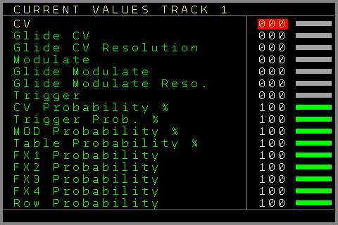
Current values of a CV/TRIGGER/MOD track:
CV → Current CV value (not the note value)
Glide CV → Current Glide setting for the CV
Glide CV Resolution → Current Glide Resolution setting for the CV
Modulate → Current MOD value
Glide Modulate → Current Glide setting for the MOD
Glide Modulate Resolution → Current Glide Resolution setting for the MOD
Trigger → Current/Last trigger setting. Can be triggered with the OK button
CV Probability % → Current Probability setting for the CV
Trigger Prob. % → Current Trigger Probability setting
MOD Probability % → Current Probability setting for the MOD
Table Probability % → Current Table Probability setting
FX1 Probability → Current FX1 Probability setting
FX2 Probability → Current FX2 Probability setting
FX3 Probability → Current FX3 Probability setting
FX4 Probability → Current FX4 Probability setting
Row Probability → Current Row probability setting
Current values for the audio tracks:
Note 1 Probability % → Current probability settings for the note of the first sample/waveform
FX 1>1 Probability % → Current FX1 Probability setting for the first sample/waveform
FX 1>2 Probability % → Current FX2 Probability setting for the first sample/waveform
Note 2 Probability % → Current probability settings for the note of the second sample/waveform
FX 2>1 Probability % → Current FX1 Probability setting for the second sample/waveform
FX 2>2 Probability % → Current FX2 Probability setting for the second sample/waveform
ROW Probability % → Current Row Probability setting for the whole sequencer row
Current values of a Trigger16 track:
CV → Current CV value of the local track
Glide CV → Current Glide setting for the CV of the local track
Glide CV Resolution → Current Glide Resolution setting for the CV of the local track
Modulate → Current MOD value of the local track
Glide Modulate → Current Glide setting for the MOD of the local track
Glide Modulate Resolution → Current Glide Resolution setting for the MOD of the local track
Trigger → Current/Last trigger setting for the local Trigger. Can be triggered with the OK button
TR1+2 Probability % → Current probability setting for Trigger column 1+2 (including drum-matrix)
TR3+4 Probability % → Current probability setting for Trigger column 3+4 (including drum-matrix)
TR5+6 Probability % → Current probability setting for Trigger column 5+6 (including drum-matrix)
TR7+8 Probability % → Current probability setting for Trigger column 7+8 (including drum-matrix)
FX1 Probability % → Current FX1 Probability setting
FX2 Probability % → Current FX2 Probability setting
FX3 Probability % → Current FX3 Probability setting
Row Probability % → Current Row probability setting
Current values of a CV16 track:
CV → Current CV value of the local track
Glide CV → Current Glide setting for the CV of the local track
Glide CV Resolution → Current Glide Resolution setting for the CV of the local track
Modulate → Current MOD value of the local track
Glide Modulate → Current Glide setting for the MOD of the local track
Glide Modulate Resolution → Current Glide Resolution setting for the MOD of the local track
Trigger → Current/Last trigger setting for the local Trigger. Can be triggered with the OK button
CV1 Probability % → Current probability setting for CV column 1
CV2 Probability % → Current probability setting for CV column 2
CV3 Probability % → Current probability setting for CV column 3
CV4 Probability % → Current probability setting for CV column 4
CV5+6 Probability % → Current probability setting for CV column 5+6
FX1 Probability % → Current FX1 Probability setting
FX2 Probability % → Current FX2 Probability setting
FX3 Probability % → Current FX3 Probability setting
Row Probability % → Current Row probability setting
Current values of a Midi track:
CV → Current CV value of the local track
Glide CV → Current Glide setting for the CV of the local track
Glide CV Resolution → Current Glide Resolution setting for the CV of the local track
Modulate → Current MOD value of the local track
Glide Modulate → Current Glide setting for the MOD of the local track
Glide Modulate Resolution → Current Glide Resolution setting for the MOD of the local track
Trigger → Current/Last trigger setting for the local Trigger. Can be triggered with the OK button
Note 1 Probability % → Current probability setting for Midi Note 1
Note 3 Probability % → Current probability setting for Midi Note 3
Note 2 Probability % → Current probability setting for Midi Note 2
Note 4 Probability % → Current probability setting for Midi Note 4
FX1 Probability % → Current FX1 Probability setting
FX2 Probability % → Current FX2 Probability setting
FX3 Probability % → Current FX3 Probability setting
Row Probability % → Current Row probability setting
Current values of a I2C/Multi track:
CV → Current CV value of the local track
Glide CV → Current Glide setting for the CV of the local track
Glide CV Resolution → Current Glide Resolution setting for the CV of the local track
Modulate → Current MOD value of the local track
Glide Modulate → Current Glide setting for the MOD of the local track
Glide Modulate Resolution → Current Glide Resolution setting for the MOD of the local track
Trigger → Current/Last trigger setting for the local Trigger. Can be triggered with the OK button
COL1 Probability % → Current probability setting for Column 1
COL2 Probability % → Current probability setting for Column 2
MATRIX1 Probability % → Current probability setting for Matrix Column 1
MATRIX2 Probability % → Current probability setting for Matrix Column 2
MATRIX3 Probability % → Current probability setting for Matrix Column 3
FX1 Probability % → Current FX1 Probability setting
FX2 Probability % → Current FX2 Probability setting
FX3 Probability % → Current FX3 Probability setting
Row Probability % → Current Row probability setting
Current values of a Dualchord track:
CV → Current CV value of the local track
Glide CV → Current Glide setting for the CV of the local track
Glide CV Resolution → Current Glide Resolution setting for the CV of the local track
Modulate → Current MOD value of the local track
Glide Modulate → Current Glide setting for the MOD of the local track
Glide Modulate Resolution → Current Glide Resolution setting for the MOD of the local track
Trigger → Current/Last trigger setting for the local Trigger. Can be triggered with the OK button
COL1 Probability % → Current probability setting for Column 1
COL2 Probability % → Current probability setting for Column 2
COL3 Probability % → Current probability setting for Column 3
COL4 Probability % → Current probability setting for Column 4
Col Trigger Probability % → Current probability setting for Trigger Column 1
FX1 Probability % → Current FX1 Probability setting
FX2 Probability % → Current FX2 Probability setting
FX3 Probability % → Current FX3 Probability setting
Row Probability % → Current Row probability setting
The probability settings are always shown in the range of 0 – 100% here.
14
Table screen
A Table is a kind of sequencer within the sequencer. It can run next to your main pattern of the track and can be used for different purposes like generating arpeggios, generative sequences, manipulation of the main pattern, special ratcheting, off-step manipulation or FX execution, special gating sequences and much more…
Tables are also able to create their own sequences. A table sequence is up to 16 steps long (but tables can be chained, so longer table sequences are possible) and can be started from the table column in a CV/Gate, Midi or CV16 track, and via the Table FX command in all track types.
All tracks can run their own table and flexibly switch, start or stop it.
- Hop to row
- Transpose
- Effect
- Table number
- Track type the table is assigned to
- Source and speed
- Sequence type
- Main pattern column(s) followed
- Random range
- Allowed notes
- Quantise to the allowed notes
- Set the allowed notes from a chord
- Status text: what the field under the cursor does
- Row
- Hop back to row
00
A table sequence can run synchronised to the main sequencer, can be free running without any relation to the sequencer tempo, can be clocked through the CV inputs, through the Automators, by the mappings or from the sequencer with an FX command. Additionally, different time dividers and multipliers can change the table timings. A table can also run in different directions/modes: forward, backward or pingpong. There can be only one running table per track. If you use different tables in your sequence on one track, the table position will continue to run in the looping modes. Only the one-shot or resync tables will be reset to zero on table change. Multiple columns of the main pattern can be used for transposition (note columns) or triggering (Trigger16 columns). The used/affected columns of the pattern sequence can be set up per table. More info about that in the transpose column description.
A table screen has the following columns:
- HP → Hop. Here you fill in to which row the sequencer should jump (hop). In the example in the picture, there is a 00 filled in on row 06, which means that when the sequencer reaches row 06 it will jump back to 00. Note that it doesn’t play the row with the hop but jumps directly to the new row and plays it. In this case it will be a 6-step sequence (one shot), or it will iterate between the 6 steps if the loop setting is endless or restart.
Besides the ability to enter the row to jump to, there are 2 additional special commands.
RU → Random upper jump. Jumps to a random position higher than the last RU command.
So if an RU is filled in on row 05, then it would jump to a random position between 00 and 04. Multiple RU commands can be added and the RU on the highest row defines the jump ‘range’.
RD → Random jump. This one jumps directly to any random position within the 16 rows.
The RD and RU commands can be found by either entering a value below 00 or by pressing SHIFT+DELETE multiple times (toggles between functions)
- TPS / TRG → Transpose / Trigger. This column has different functionality depending on the track type. For a Trigger16 track it is used to define the trigger it should play.
You can choose between ***, which means no trigger/retrigger, and the values 00 to FE, which define the trigger/retrigger type and are the same as in the trigger columns of a Trigger16 Track.For all other track types it transposes the currently playing note(s) of the current track by a number of semitones (in combination with one or more Note columns). ‘—’ means no transposition, +1 transposes 1 semitone higher, +2 transposes 2 semitones higher etc.
Values below ‘—’ transpose lower: -1 by 1 semitone, -2 by 2 semitones etc.
While CV values and oscillator pitches are simply changed by the transposition, a Midi note will always be retriggered, since Midi has no such thing as a note change without a new Note Off and Note On. A Midi table will also always retrigger if there is no transposition defined like this: ‘—’.Next to the ‘transpose by semitones’ functionality other special commands can be reached by pressing SHIFT+DELETE multiple times (toggles between functions):
RND → Randomize. This will generate a random transposition. Combined with this function is the ‘RANGE’ setting which sets the lowest and highest value of the random range. With this you can limit the range to octaves or whatever range you choose. A random semitone transposition will then be chosen at the RND point.
>>> → This is a special command which replaces the current note with a note selected in the allowed notes section on the right side. Every >>> takes the next allowed note. For example, say you have 3 notes filled in as allowed: C#, E and A.
The first >>> would play C#, the second >>> would play E and the last one would play A. This makes it possible to create fixed arpeggio chords regardless of the main note playing.
*** → Avoid a retrigger. This command is available for Midi tables, which will then not retrigger on this row.
The Transpose/Trigger column in combination with the selected/enabled columns will affect the following pattern columns (by tracktype):
Modular → Note and MOD (if used with notes) columns
Audio → Note1 and Note 2 columns
Midi → Midi Note columns 1,2,3 and 4
Multifunctional/I2C → Pattern columns 1 to 6 (if used with notes)
CV16 → The 6 CV16 columns/destinations (if used with notes)
Trigger16 → The first 6 Trigger columns (1-6 or 9-14 if swapped)
Dualchord → The first 4 Note columns for the first 4 waveforms, and columns 5+6 for the waveforms 5 and 6.
Video → There is no transpose functionality for the Video Columns
- FX → Effect parameters. All the possible effect parameters can be added here to enable full manipulation by using the tables. All FX values of the current track type are available. Use this, for example, if you want to create a ratchet effect for your notes by choosing the trigger as FX and placing these in the order of sequencing to play doubles, triplets etc.
With the Table FX another table can be started which allows table chaining if 16 Table steps are not enough.
Pressing the OK button on the FX command will bring you to the FX Selector menu where you can comfortably select the needed FX from a list.
Source → Defines the timing source for the sequence:
INT. Tick → The sequence ‘clock’ is derived from the internal main sequencer ticks. (6 ticks/step)
INT. Time → Uses the table’s own clock. It can run faster than the Int. Tick, but it has no relation to the main clock tempo / bpm
PTN-MAP → The table clock gets its ticks from the FX functions of a regular pattern (SPFX 0011) or from the mappings.
AUTOMAT 0..7 → The table clock gets its ticks from one of the Automators. A tick is generated by the zero crossing of an Automator.
CV IN 1..4 → The table clock gets its ticks from a rising edge of the selected CV input.
Speed → The multiplier/divider.
A setting of 1 will trigger the next step in the table sequence with every clock. A setting of 6 will trigger the next step every 6th tick which is the standard speed of a regular step in the main sequencer. So with lower settings the table sequence will run faster while higher settings will let it run slower.
Type → Defines the type of the sequencing itself:
> Resync → the table runs forward endlessly in a loop but is restarted every time the sequencer passes the table command. It stops when the table is stopped or when the complete sequencer is stopped. It continues to run if only the track is stopped.
> Loop → the table runs forward in a loop but is not restarted by the table command. It stops when the table is stopped or when the complete sequencer is stopped. It continues to run if only the track is stopped.
> Once → The table runs forward only once and then stops.
< Resync → Same as the forward Resync, but the sequence runs backwards.
< Loop → Same as the forward Loop, but the sequence runs backwards.
< Once → Same as the forward Once, but the sequence runs backwards (starts from end or first HP)
>< Loop1 → The table runs in a ping pong loop. If set as in the example picture, it runs the following sequence: 00,01,02,01,00,01,02… and so on
>< Loop2 → The table runs in a ping pong loop. If set as in the example picture, it runs the following sequence: 00,01,02,02,01,00,00,01,02,02,01,00… and so on
>< Once → Runs the ping pong sequence as in Loop1, but only once (00,01,02,01,00).
Random → The table does not run in a fixed direction but picks a random step. In the HOP column you choose whether the random step is taken from the whole table or only up to the first hop, so the randomness can be kept within a section.
Column → Defines which (note) columns should be affected by functions of the table transpose column. Up to 6 columns can be selected. The columns refer to the columns in the main pattern. A MIDI track, for example, has 4 note columns which you can manipulate individually with the column setting in the table.
The Column setting additionally chooses whether the affected notes are retriggered on every table step (Transpose cols + retrig) or not (Transpose cols no retrig). An 'R' on the Column field indicates that retrigger is active; toggle it with SHIFT+CURSOR UP/DOWN. Automatic retriggering currently works for CV/Gate and Sample tracks.
Range → As mentioned before, defines the transposing range of random values. Change the lower value with SHIFT + LEFT/RIGHT and the higher value with SHIFT + UP/DOWN.
The part below adds a special scaling to the transpositions. When a note is transposed, it can also be locked to one of the allowed notes. It will then choose the nearest allowed note instead of the transposed note. The way it chooses the nearest note can be changed in the Quantize setting. The allowed notes can each be selected by SHIFT + RIGHT/UP or deselected by SHIFT + LEFT/DOWN.
Quantize setting:
NO → Notes are not quantized to the allowed notes. Normal transposition with all possible notes is used.
UP → The next higher note of the allowed notes is taken. For example, if the new note after transposition is E-5 and the allowed notes are C, F# and A the note will be scaled to the next higher note → F#5.
LOW → The next lower note of the allowed notes is taken. For example, if the new note after transposition is E-5 and the allowed notes are C, F# and A the note will be scaled to the next lower note → C-5.
COIN → A coin toss decides randomly whether the next higher or the next lower note will be chosen.
Finally, the SET CHORD function can set the allowed notes directly to the chosen Chord. The Chord note can be changed using SHIFT +UP/DOWN and the chord type (Major, Minor, diminished, 7th) can be changed using SHIFT+LEFT/RIGHT. The selected chord can be activated by pressing the OK button. The allowed notes then change to the chord. Holding the OK button while changing the chord will result in a direct change of the allowed notes. The SET CHORD value is just a kind of preset which sets the allowed notes; it can show a different chord than the allowed notes currently contain. It always needs the OK button for the SET CHORD to be activated.
Next to the sequencer row you can see the table animation which shows on which step the table is playing right now on the available tracks. This also shows how the sequence is running.
Nerd Menu / Table Presets:
For ease of use, many standard tables can be inserted as a preset. Use the Nerd Screen / Menu in the table screen (SHIFT+NERD) to get to the presets. Navigate down to the option Preset > xxxxx
Choose one using SHIFT+LEFT/RIGHT and press OK; it will be inserted into the current table.
The following presets are available:
Empty → Clears the content of the table
Random → Inserts a random transpose sequence with a hop 00 on a random step. The random transposition range is set by the Range (lowest and highest transposition note)
Doubles → Inserts FX commands to create a double (ratcheting) for the main sequence. This creates a double trigger/gate (or envelope trigger) for the main sequence in a step. As a result, a note is triggered twice, evenly spaced, in one step. Note that this preset also changes the table clock and type settings so the timing and sequence is correct.
Triplets → Same as doubles, but this inserts 3 equal trigger/gates for a step so triplets can be played.
The following are standard chords with 3 or more notes:
Triads → Major, Minor, Diminished, Diminished 5th, Augmented, Suspended 4th, Suspended 2nd
7th Chords → Dominant 7th, Minor 7th, Major 7th, Minor Major 7th, Suspended 7th, Augmented 7th, Augmented Major 7th, 7th Augmented 9th, Half Diminished 7th, Diminished 7th, 7th Diminished 5th, 7th flat 9
6th Chords → 6th, Minor 6th
9th Chords → 9th, Minor 9th, Major 9th, 9th Diminished 5th
Plus an 11th chord and a 13th chord.
Edit Table Name → Enter this to open the on-screen keyboard and enter a name for the table. The table name will appear at the top right.
Release Table → This will empty and release a table from a track type, so it can be newly assigned.
Good to know: Use the ‘Clean Tables’ command in the Reorganize Screen to release all unused tables automatically. Keep in mind that tables with content (something in the transpose, hop or fx column) will not be released. This avoids deleting prepared tables which are temporarily unused. To release those anyway, you need to release them in the Nerd Screen / Menu from the table screen.
You can navigate between all tables by holding the TABLE button in the table screen and pressing CURSOR UP/DOWN.
The table screen has the same Mark / Copy / Paste functionality as the other screens, but additionally you can select either the columns/rows or the settings on the right side to be used for the copy/paste actions.
Also good to know:
- You can create nice FX effects by using the Add/Sub/Mul/Div commands and letting these calculations run in a table. For audio this can create time-stretching or granular effects.
- For a Midi track a special Velocity Overrule FX has been added which can create Midi delay or fading effects in combination with the Midi retriggering of a table and a decrementing or incrementing Velocity FX.
- A table can also be filled dynamically using notes from a Midi keyboard, which allows on-the-fly arpeggios. Check the Input Assign section of the Midi / I2C Setup Screen for more info.
15
Automator screen
The Automator screen contains up to 8 possible slots for Generators / Modulators / Effects / Manipulators. An Automator can currently be an LFO, Envelope, or a CV Input. You can assign an Automator to any of the 8 slots. The output of the Automator can be routed to several functions, outputs and more through a modulation matrix. The matrix has the 8 tracks as destinations, and in it you can decide which setting / function / output of each track should be modulated by the Automator. Be aware that Automators can also generate negative values (e.g. the lower half of a sine-wave LFO), and for most destinations the values are scaled and added depending on the destination’s maximum value.
- Automator function of the slot
- Started / stopped
- Selected cell: slot 0 → MOD output of track 1 (
01) - Tracks 1–8
- Status: the destination under the cursor
- Settings of the selected slot, here the LFO: speed, offset, invert, clock, amp, wave, bit and phase
- Selected slot
- Slot numbers 0–7
The top part of the screen shows the 8 slot rows: from the left, the slot number, followed by the assigned function (empty if no function is assigned to the slot). Next is the indication whether this slot/function is running or not. The 8 tracks next to it define which function of each track the output is ‘routed’ to. In the picture you can see that the LFO in slot 0 is routed to the MOD output of Track 1. In other words, the LFO is modulating the physical MOD1 output. In the middle of the screen you can see the animation of the currently selected Automator.
The lower part shows the settings of an Automator. The screenshot shows the LFO with all its settings.
The current version has the following Automator functions:
- LFO
- Envelope
- CV Input/Output
The destinations in the modulation matrix for the CV/Gate tracks are:
- CV Output → Modulates the function onto the CV output
- MOD Output → Modulates the function onto the MOD output
- Trigger Length → Overrides the next trigger setting with an ON/OFF trigger, where the length of the trigger is determined by the Automator output (10 .. C0)
- Delayed Trigger/Gate length → Overrides the next trigger setting with an OFF/ON trigger / gate, where the length of the delay is determined by the Automator output (01 .. 0F)
- FX1..FX4 Overrule → Overrides the next FX of the defined FX column by the value of the Automator
- CV Glide → Manipulates the Glide setting for the CV output
- CV Resolution → Manipulates the Glide Resolution setting for the CV output
- MOD Glide → Manipulates the Glide setting for the MOD output
- MOD Resolution → Manipulates the Glide Resolution setting for the MOD output
- CV/Trigger/MOD/Table/FX1..4/Row Probability → Manipulates the probability settings for the defined FX
- Step Overrule → Overrides the current step in the currently playing pattern. This is an experimental function.
- Gate → Sets or resets the gate of the selected track. If the Automator value is higher than 0, it sets the gate, and if it is lower than 1, it resets the gate.
- Trigger → Nearly the same as Gate, but instead of gating, only a trigger is generated on the low-to-high transition
The destinations for the audio tracks 7+8 are:
- Pitch → Modulates the pitch of the currently playing sample/wave for either the first or the 2nd sample/wave in the pattern screen
- Volume → Modulates the Volume
- Bitcrush → Modulates the bitcrush settings
- Distortion → Modulates the distortion settings
- Position → Manipulates the current sample offset/position (funny time-stretching effects are possible with that). In combination with a pulse wave, it modulates the pulse width
- Wavefold → Manipulates the wavefold settings of the sample/waveform
- Overrule FX1..4 → Overrides the next FX value
- Probability % → Manipulates the probability settings for the Samples 1/2
- Probability FX → Manipulates the probability settings for the defined FX
- Probability Row → Manipulates the probability settings for the whole track row
- Overrule Steps → Overrides the current step in the currently playing pattern part. This is an experimental function.
All audio destinations are for either the 1st or for the 2nd sample/wave of an audio track except for the row probability, which applies to both.
The destinations in the modulation matrix for the Midi assigned tracks are:
- Pitchbend → Sends pitch bend data to the Midi device.
- CC1..8 → Sends CC data to the controller numbers which are set up in the Midi track settings
- NRPN1..4 → Sends NRPN data to the controller numbers which are set up in the Midi track settings
- Note overrule → Not implemented yet
- The rest are the same as for a regular CV/Gate track, with the following exceptions:
– Probabilities are set to the Midi note and FX groups.
The destinations in the modulation matrix for the ‘Trigger16’ expander assigned tracks are:
- Trigger 1..4 Length → Overrides the next trigger (of the expander), where the length of the trigger is determined by the Automator output (10 .. F0)
- Delayed Trigger/Gate 1..4 length → Overrides the next trigger (of the expander) with an OFF/ON trigger / gate, where the length of the delay is determined by the Automator output (01 .. 0F)
- Triggers Galore → Sends triggers (as set up in the track setup) to the trigger output corresponding to the current value of the Automator output.
- Triggers Square 8 → Uses the Automator output to set and reset Trigger output 8 (or 16 if swapped). If the Automator output is higher than 0, the output is set, and if it is lower than 0, the output is reset. Only applies to outputs 8 or 16!
- The following destinations are the same as for a regular CV/Gate track, with the following exceptions:
– Probabilities are set to the trigger output and FX groups. - Trigger 1..16 Gate – Sets a gate on the defined Trigger16 output if higher than 0; otherwise it resets the gate
- Trigger 1..16 Trigger – Generates a Trigger on the defined Trigger16 output with every low-to-high transition
The destinations for the CV16 tracks are:
- CV 1..16 → Modulates the function onto the CV outputs 1..16
- Column 1 Probability → Probability for Column 1 of the pattern screen
- Column 2 Probability → Probability for Column 2 of the pattern screen
- Column 3 Probability → Probability for Column 3 of the pattern screen
- Column 4 Probability → Probability for Column 4 of the pattern screen
- Column 5+6 Probability → Probability for Column 5+6 of the pattern screen
- FX1..3 Probability → Probability for the FX1..3 column
- FX1..3 Overrule → Overrides the values of the FX1..3 column
- Envelope 1..8 Attack/Sustain/Release → Modulates the envelope settings
- LFO 1..8 Type/Speed/Amplitude → Modulates the LFO settings
- Local CV → Modulates the local CV output of the track-setup
- Local MOD → Modulates the local MOD output of the track-setup
- Local Glide (CV/MOD) → Modulates the local glide settings
- Row Probability → Modulates the probability of the complete pattern row
- Local Gate → Sets and resets the local gate of the track
The destinations for the I2C tracks are:
- Column 1-6 Destination → Sends the data to the destination defined for Column 1-6 of the track
- Matrix 1-16 Destination Gate → Sets or resets a Gate (zero cross) to the destination defined for the Matrix 1-16 of the track. Trigger only destinations fire on the rising edge.
- Column123 Probability → Probability for the columns 1, 2 and 3 of the pattern screen
- Column456 Probability → Probability for the columns 4, 5 and 6 of the pattern screen
- Matrix1, Matrix2, Matrix3 Probability → Probability for the first three columns of the drum matrix. The matrix columns 4 to 16 have no probability setting and always play.
- FX1, FX2, FX3 Probability
- FX1, FX2, FX3 Overrule
- Local CV
- Local MOD
- Local CV Glide
- Local CV Resolution
- Local MOD Glide
- Local MOD Resolution
- Row Probability
The destinations for the Dualchord tracks are:
- Wave1..8, 1-4, 5-8 Pitch
- Column 1 Probability
- Column 2 Probability
- Column 3 Probability
- Column 4 Probability
- Trigger Column1 Probability
- FX1,2,3 Probability,
- Row Probability
- FX1,2,3 overrule
- Stereo Deepness
- Wave1..8, 1-4, 5-8 Pulsewidth
- Wave1..8, 1-4, 5-8 Detune
- Wave1-4, 5-8 Spread
- Wave1..8, 1-4, 5-8 Triangle Mix
- Wave1..8, 1-4, 5-8 Sine Mix
- Wave1..8, 1-4, 5-8 Saw Mix
- Wave1..8, 1-4, 5-8 Pulse Mix
- Wave1..8, 1-4, 5-8 Morph
- Wave1..8, 1-4, 5-8 Glide
- Dualchord Trigger 1 Gate
- Dualchord Trigger 2 Gate
- Local CV
- Local MOD
- Local CV Glide
- Local CV Resolution
- Local MOD Glide
- Local MOD Resolution
- Local Gate
The destinations for the Video tracks are:
- Modulator 1..16
- Position X / Y
- Time Amplify
- Alpha
- Pen X/Y (beta, use with caution)
- Circle X/Y (beta, use with caution)
- Color Red/Green/Blue (beta, use with caution)
- Bar X/Y (beta, use with caution)
- Local CV/MOD
- FX1,2 Overrule
- Local CV Glide
- Local CV Resolution
- Local MOD Glide
- Local MOD Resolution
- Column 1,2, FX 1,2, Row probability
You can change the Slot and Modulation settings by using SHIFT + LEFT/RIGHT.
Toggle Start/Stop by pressing OK.
Start by using SHIFT + CURSOR RIGHT.
Stop by using SHIFT + CURSOR LEFT.
To get to the Automator settings below you can either press OK on the Automator function or use the DOWN button. To get back, use the UP button.
In the Automator settings you can navigate between the settings and change values with SHIFT + LEFT/RIGHT. For the LFO, if the cursor is on the RST field, an LFO reset can be triggered by pressing OK.
Automator functions
The following Automator functions are currently implemented:
LFO
A low frequency oscillator with several waveforms and many parameters. The LFO is continuously running but can be started/stopped through the slot start/stop.
There are 2 ways to manipulate the parameters of the LFO. First, by using the slot editor at the bottom of the Automator screen, and second, through the Automator slot manipulation commands in the FX column of the sequencer.
LFO Parameters and characteristics:
- Waveforms: Sine, Triangle, Sawtooth, Pulse, White Noise, Walking Noise and the 12 Sample slots (SMPL 0 .. SMPL B)
The Walking Noise replaces the former Pink Noise. It is a random walk which moves smoothly around the middle point instead of jumping around like the white noise does. For this waveform the Phase parameter is used as the intensity/deepness of the ‘walk’.
If you select one of the 12 sample slots as the waveform, the sample itself is used as the LFO waveform. The complete sample is one full LFO cycle, so the length of the sample defines the length of the cycle and all clock synchronised LFO settings stay exact.
Instead of using samples from the sample pool you can generate your own samples / waveforms (a kind of CV recorder). To do so, press OK on a selected filled or empty sample. This will get you to the Automator Record settings.
Next to the WAVE field the current waveform is drawn, including the phase marker and the inverted view, so you can always see what the LFO is doing.
- Clock sources:
- Free running
- Slow → Same as free running, except that the speed is 100 times slower.
– Tick → Clock is synchronized to the sequencer ticks. If speed is set to 1, then one LFO waveform cycle has the same length as one pattern while the LFO advances with every tick.
– Pattern → Clock is synchronized to the pattern rows. If speed is set to 1, then one LFO waveform cycle has the same length as one pattern while the LFO changes with every pattern row (derived from main clock). The effect is a kind of stepped LFO. - Slot 0..7 → The clock is derived from the output of another slot, and the speed parameter works as a divider. This can be used to achieve frequency modulation (FM), with the frequency modulated by another slot.
- STP-MUL → Advances the LFO waveform with every main clock sequencer step with a multiplier. The multiplier is set with the Speed parameter.
- STP-DIV → Advances the LFO with every sequencer step divided by the divider which is set up in the speed field.
- TCK-MUL → Same as STP-MUL, but with the higher resolution of ticks.
- TCK-DIV → The same, but with a divider.
- STP-SLT → Advances a step on the LFO based on the zero cross of another slot (which could be for example an external CV clock). The slot is selected with the speed parameter. (e.g. speed 1 means slot 1 as the source).
- n*STEP → Advances the LFO waveform n times per step (number of times set via speed)
- STEPS → One full LFO waveform lasts one or multiple steps (number of steps set via speed).
Please be aware that n*STEP and STEPS don’t run at exact step times, so a reset (resync) of the LFOs might be needed if you want to run them for a longer time. This is caused by the nature of the Automators and their different refresh rate. A reset/resync might also be needed after starting a sequence, since the LFOs are free running and keep running even when the sequencer is stopped. The STEPS clock is an exception here: as long as the selected number of steps fits into the mainclock, the LFO is reset on the zero cross of the mainclock (and so also on a sequencer start), so it always stays locked to the pattern. Longer cycles keep running free as before. - Speed → Defines the speed / frequency of the LFO. If the clock is set to Tick, Pattern or Slot, the speed value acts as a divider. Note that the speed for the noise waveforms has a different scale than the ones for the periodic waveforms.
- Amplitude (AMP) → Defines the Range / Amplitude of the LFO. The value goes up to F7, which is the maximum amplitude. Slot0..Slot7 can be defined as the source for the range. With that you can achieve Amplitude Modulation (AM).
- Offset: Adds or subtracts a DC Offset to the LFO waveform.
- Invert → Inverts the LFO Waveform
- Bit → Resolution of the LFO waveform. 1 bit to 12 bit
- Phase → Sets the Phase/Offset of the waveform. So when the LFO is started/reset it will start from this point in the waveform. In combination with the pulse wave it decides the pulse width. For the Walking Noise waveform this field is named DEEP and it sets the intensity of the random walk.
- Rst X → Resets the waveform to its start or, more precisely, to the phase position of the waveform. With Rst X there is no source, and the LFO can only be reset by pressing OK on the function or from the sequencer Automator FX functions (ASLx 101). You can also set the Rst X value from 0 to 7, which means that the reset will additionally be triggered by another slot. To trigger a reset, the reset input needs a transition from 0 (or lower) to at least 200, which is approx. 0.5 Volt in the 10 Volt range. Internally it means that the output of another Slot must have been 0 or lower and go to output values of 200 and higher. By using a CV input as another slot Automator, one can reset the LFO from an external source.
- CV Input / Output (CV I/O) → These Automators can use the CV inputs as well as the CV or MOD outputs as their source and route it to any of the Automator destinations or to other slots. This can be used to manipulate many internal values of the sequencer by an external source and by the current values of the CV/MOD outputs.
The following settings are available for the CV inputs:
- Source → CV input 1..4 uses the CV Input Jacks as an Automator source;
OUT CV1..6, MOD CV1..6 use the CV/MOD outputs (same signal) as an Automator source. Be aware that this is the signal including any Automator manipulation. - Offset → Adds or subtracts a DC Offset to the Source
- Invert → Inverts the Source signal.
- Amplitude (AMP) → Defines the Range / Amplitude of the source. A value of F7 will use the full CV range of 0 to 10 Volt. Furthermore, the outputs of the Automator slots 1..8 can be used to manipulate the Range/Amplitude.
- Bit → Resolution/Quantisation of the Source. 1 bit to 12 bit
- Source → CV input 1..4 uses the CV Input Jacks as an Automator source;
- Envelope
The envelope Automator function can manipulate and route the envelopes through the Automator functions and modulation matrix. Note that this is not an envelope generator within the Automators, but rather uses the output of the integrated envelopes of the NerdSEQ to route into the Automators. With this the envelopes can be additionally manipulated and will also get the resolution of the Automators (within the Automators only, the normal envelope works as is). Use this to achieve some special effects with the usual envelopes or to route them in a different way through the modulation matrix. You can see the current curve of the selected envelope on the bottom right. You need to use the Envelope screen to edit the envelope curve.
The following settings are available for the Envelopes:
- Input → Chooses which envelope (1..8) should be used
- Offset → Adds or subtracts a DC Offset to the Envelope
- Invert → Inverts the envelope curve.
- Amplitude (AMP) → Defines the Range / Amplitude of the Envelope. A value of F7 will use the full Envelope range. Furthermore, the outputs of the Automator slots 1..8 can be used to manipulate the Range/Amplitude.
- Bit → Resolution/Quantisation of the Envelope. 1 bit to 12 bit
Please note that the Automator LFOs and envelopes can never replace a true analogue or digital LFO/envelope module. The Automators have a limited resolution, with all its side effects. However, they are still great modulation sources for any internal and external modulations.
16
Automator Record
With the Automator Record you can record a modulation / motion into one of the 12 sample slots and use it afterwards as an LFO waveform. In effect, this is a CV recorder. Nearly everything that runs inside the NerdSEQ can be recorded: the CV inputs (0-10 Volt), the CV and MOD outputs, any mapping row or any of the 16 variables. The result is a 12 bit sample which is locked to the mainclock, so a recorded shape always stays musically in sync, no matter what tempo you play it back at later.
You reach the Automator Record from the Automator screen. Choose an LFO in one of the 8 slots, go to the WAVE field and select one of the sample slots (SMPL 0 .. SMPL B). The status line then shows ‘PRESS OK TO RECORD’, and pressing OK opens the Automator Record window.
The following settings are available:
- STEPS → The length of the recording in mainclock steps. Every step contains 32 recorded frames, and next to the value you can see how many bytes the recording will use. The maximum length depends on the free sample memory.
- SOURCE → The source that should be recorded: CV IN 1..4, CV OUT 1..6, MOD OUT 1..6, one of the mapping rows (shown as MAP xx followed by the name of the source of that row) or one of the variables A..P.
- RECORD → Starts the recording. The recording is armed and waits for the next zero cross of the mainclock (the status shows ‘STARTING IN -xx’) and then records for the selected number of steps (‘RECORDING xx/xx’). If you stop the sequencer in the meantime, the recording is finished with what has been recorded so far.
- ABORT → Leaves the window again. After a finished recording this entry is named FINISH.
The recorded sample gets the name ‘AutoRecX’ (where X is the slot number) and is stored as a 12 bit sample. While the window is open the slot is pre-listened through the LFO output, so you can already hear the modulation while it is being recorded.
Recorded samples can be used in the Automator and also for sample playback in the audio tracks.
If the Automator Record window is already open on an unarmed RECORD row, SHIFT+RECORD or a mapping row set to Arm/disarm recording (MREC) arms it too, exactly like pressing OK on that row: the sequencer starts (or the pre-roll countdown runs) as usual, and the recording still waits for the next zero cross. Once the recording finishes, the general Record mode switches itself off again.
17
Envelope screen
The NerdSEQ also includes an envelope generator which is capable of generating 8 different ADSR envelopes. Each envelope has functions to manipulate its curve and behaviour. To start the envelope, several internal and external sources can be used in flexible ways. Many internal functions and all external CV and MOD outputs can be set as destinations.
You can enter the envelope screen by pressing the AUTOMATE button when in the Automator screen (the AUTOMATE button toggles between the automator and the envelope screen).
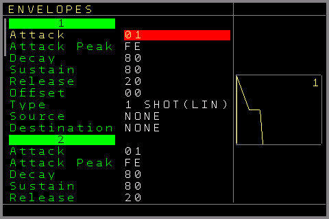
In the envelope screen you can navigate between the 8 envelopes. The UP/DOWN buttons jump directly to the next envelope. To change parameters use the usual SHIFT+LEFT/RIGHT/UP/DOWN. All settings except the sources and destinations are active immediately. The sources and destinations are only activated when pressing the OK button on them or when leaving the envelope screen.
The following functions are available for each envelope:
Attack → Defines the Attack speed.
Attack Peak → Defines the maximum amplitude level of the attack phase.
Decay → Defines the decay speed.
Sustain → Defines the amplitude level of the sustain phase.
Release → Defines the release speed.
Offset → Defines the start and the end level of the envelope. The Attack phase starts from this level and will either rise or fall to the Attack peak level. The Release phase ends on the offset level (also either by rising or falling, depending on the sustain level). Use the Offset to create more complex envelope curves, but be aware that an envelope will end on the offset level and it will stay there. A VCA may ‘stay open’ depending on the offset level, and waveforms can still be audible after the release phase if the offset is not set to zero.
Type → Defines the way the envelope runs as well as the envelope curve.
One Shot (LIN/EXP) → Here the envelope only needs to be triggered/gated once, and it will run the ADSR phases in one go: Attack → Decay → Sustain Level → Release. There is no pause at the sustain level and the release starts directly after the decay phase reaches the sustain level.
AD-SR (LIN/EXP) → This starts the envelope with a gate signal (or a virtual gate generated internally → sources), and it stays in the sustain phase (after decay has reached the sustain level) until the gate is released again. Keep in mind that the release phase starts immediately when the gate is reset. So if any phase was not finished, it will directly continue to release.
Loop (LIN/EXP) → The envelope keeps looping (running through all phases as in One Shot mode) as long as the gate is set.
Each of the three types is available with a linear (LIN) or an exponential (EXP) response. (3x LIN, 3x EXP). The exponential variants give a more natural, snappier curve for the attack, decay and release stages, while the linear variants ramp evenly.
Source → Defines the source from which the envelope can be triggered / gated.
Gate 1..6 → will derive the trigger/gate from the tracks 1..6. (for example, when playing a note on the track, a gate is also set for the envelope; a note off will release the envelope if in AD-SR mode).
T7 Audio1,2 and T8 Audio 3,4 → The start of a waveform or sample on track 7 or 8 (audio part 1,2,3,4) will ‘gate’ the envelope. When the sample has finished, the gate is released.
A special reset gate command (***) in the note column of an audio track can release the gate before the sample/waveform is finished, which will start the release phase of the envelope while the sample continues to play.
A special note off command ([ ]) in the note column of an audio track can stop playback of the sample/waveform before it is finished and simultaneously start the release phase of the envelope if in AD-SR mode.
CV IN 1,2,3,4 → The CV inputs can be used to set/reset the gate for the envelope.
ENV1..8 Start → The start of the selected envelope will also start this envelope. This can be used to have multiple envelopes start at the same time.
ENV1..8 End → When the selected envelope has finished, it will start this envelope. This allows chained envelopes to be created.
Clone ENV 1..8 → This will exactly clone the generated envelope so you can use it for multiple destinations. Note that the envelope curve settings have no effect here.
Destination → Defines the destination that the envelope should manipulate.
CV 1..6 → The envelope will be routed to the CV outputs 1..6
MOD 1..6 → The envelope will be routed to the MOD outputs 1..6
Volume 1..4 → The envelope will act as a VCA on the selected audio channel (e.g. on samples/waves)
Pitch 1..4 → The envelope will override the pitch of the selected audio channel
Bitcrush 1..4 → The envelope will override the bitcrush of the selected audio channel
Distort 1..4 → The envelope will override the distortion of the selected audio channel
Wavefold 1..4 → The envelope will override the wavefold of the selected audio channel
The Source and the Destination settings are activated by pressing the OK button or by leaving the envelope screen. SHIFT+DELETE on them will set them to ‘none’.
If routed through an Automator, more manipulation of the envelope is available, and it can also be routed through all Automator destinations. Keep in mind that the rate (as in processing-rate/resolution) of the envelope will degrade to the Automator’s processing rate.
Besides the fixed sources, an envelope can also be gated through FX commands.
You can see an animation of the currently selected envelope’s stages when it is running.
Envelopes and their settings can also be triggered/started/changed from the patterns at runtime or from the mappings.
18
Project screen
The project screen contains project-related functions which can be different for each project. Its settings will be loaded and saved when loading/saving a project.
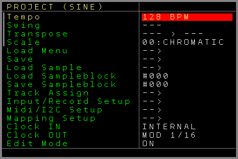
The following menu items are available:
Tempo → Changes the global tempo between 1 and 500 BPM. (SHIFT + LEFT to decrease, SHIFT + RIGHT to increase).
Additionally, it contains a Nudge function. Nudging is what a DJ does…..or used to do 😉 ….to synchronize records with each other by pushing or briefly slowing down the record. Holding SHIFT+OK and then CURSOR UP/DOWN, will roughly nudge the sequencer forward and backward and with CURSOR LEFT/RIGHT it will finely nudge the sequencer forward and backward.
Swing → Adds swing/groove to the global mainclock with ±1/64th precision. Please note that the clock outputs are also affected by the swing. Also, the swing is only active with the internal clock and is deactivated with any external clock.
Transpose → Changes the global transpose in semitones/octaves above or below the regular pitch. When changing the value with SHIFT+CURSOR LEFT/RIGHT, the new transpose value will be applied on the next zero transition of the mainclock if the sequencer is running. Pressing OK will change the transpose value immediately. Holding OK while pressing SHIFT+CURSOR LEFT/RIGHT will also change the transpose immediately.
Scale → Select from a wide range of scales to scale/quantize notes. Press SHIFT+CURSOR LEFT/RIGHT to change the selected global scale, or press OK to enter the Scale Screen which allows you to customize more scaling settings.
Load Menu → Opens a file browser to load a project.
A project file can also be deleted from the file browser (SHIFT+DELETE). It is moved into the Backup folder instead of being erased, so it can be recovered if needed.
Save → Saves a project. An on-screen keyboard will appear to either save the current project (just press OK on the READY field) or enter a new project name and save it by pressing OK on the READY field. An existing project will be overwritten after a backup has been created in the backup folder (10 iterations).
Load Sample → Opens the sample slot window.
Load Sampleblock and Save Sampleblock → Load and save complete sample blocks. A sample block consists of all 12 sample slots together. Here you can recall the whole block (e.g. replace all samples in one go). This can also be loaded nearly seamlessly while running a sequence using a command in the sample FX.
Sample block 000 is not supported, so every sample block must be numbered 1 or higher.
Track Assign → Enters the Track Assign Screen. This is used to assign different track types to the tracks. For example, a regular CV/Gate track can be set to be a Midi, Trigger16, CV16 or any other track type to use its dedicated functionality.
CV Input/Gamepad Screen → To set up all CV inputs for recording or live manipulation CV Input/Gamepad Screen
MIDI / I2C Setup Screen → To set up Midi-related functions like input, recording, filtering, clock and more. The main I2C port settings are also in the Midi / I2C Setup Screen
Mapping Setup Screen → To set up all kinds of mappings from sources to destinations, or to manipulate all kinds of internal and external values with simple but useful coding features. Mapping Screen
Clock IN → The main clock input setting. The options are:
- Internal → Sequencer runs from the internal clock at 24ppqn internally
- Mod. Clock24 → Sequencer runs from the Clock/Reset input with a resolution of 24ppqn
- Mod. Clock → Sequencer runs from the Clock/Reset input with 1/16 resolution
- Midi TRS-A → Sequencer runs from external Midi Clock from the TRS-A or regular DIN Midi Port as follower (Midi-IO Expander / TRS-A Midi expander / Multi-IO expander module needed)
- DIN-Sync → Sequencer runs from external DIN-Sync signals where the clock input is the DIN-Sync clock signal and the reset input is the DIN-Sync run/start/stop signal. The continue signal is not supported.
- Midi USB-DEV → Sequencer runs from external Midi Clock from the USB Device port as follower (Multi-IO expander module needed)
- Midi USB-HOST → Sequencer runs from external Midi Clock from the USB-Host port as follower (Multi-IO expander module needed)
If an external clock source is selected and the sequencer is playing, the clock source can be changed directly to Internal by pressing SHIFT+DELETE. This is used to switch seamlessly to the internal clock while maintaining the same BPM (best effort).
Clock Out → The clock output settings. The options are:
- MOD 1/16 → Standard modular clock with 1 clock per step
- DINSYNC24 → Outputs 6 clocks per step. Same as DIN SYNC (Reset is high when started and low when stopped).
- DISABLED → Disables the clock output. The Clock and Reset outputs can be either used as additional Trigger/Gates or to generate a user defined clock from a sequence.
The settings to send Midi-Clock are in the Midi / I2C Setup Screen
Edit Mode → On/Off. Prevents editing, for example while playing live or demonstrating. No patterns can be changed when edit is off. However, playing live is still possible. Some extra functions with live playing are enabled when edit is turned off.
Reorganize → Enters the Reorganize Screen which has options to clean / sort patterns, tables or patches.
Live Cue points → The number of steps after which a new pattern is started (derived from the main 64-step clock). Normally, a newly triggered pattern starts when the old pattern sequence has finished. With live quantisation, which you enable by pressing START twice to trigger a new pattern, the new pattern will start from the next Live Cue point. You can see the live cue points at the top and bottom of the sequencer in the main clock bar.
Main clock → Sets the number of main clock steps. It also defines the maximum length a pattern plays. While the standard is 64 steps, fewer steps can be used for different rhythmic variations. By pressing the OK button on this field (or holding it while changing the value), all tracks will be synchronized to the current clock position. This only works well if the tracks are equal, not if they have odd groove settings which differ from the standard groove. SHIFT+CURSOR LEFT/RIGHT increases/decreases the value by one. Increasing using SHIFT+CURSOR UP increases in the following step pattern: 2,4,8,16,32,64. Decreasing using SHIFT+CURSOR DOWN decreases in the following step pattern: 32,16,8,4,2,1.
NerdScope → Enters the Scope Screen (NerdScope), a simple built-in 4-channel oscilloscope.
Backup/Restore → Allows files from the SD Card to be backed up onto your computer and project/firmware/wavefiles to be uploaded onto the SD Card via one of the Midi ports. Use SHIFT+CURSOR LEFT/RIGHT to choose the MIDI destination (TRS, USB Host or USB Device). With the Multi-IO, the easiest way is to use the USB DEVICE port, which offers a direct connection to the NerdSEQ Backup tool.
- Backup Projectfiles → Opens the file browser, where you can back up a single selected file (OK), back up every file in the current folder (SHIFT+OK), or enter a sub-folder to back up files from there. The NerdSEQ Backup tool will automatically save all received files.
- Restore / Receive Files → Sets the NerdSEQ to file receive mode. The NerdSEQ Backup tool allows you to upload all NerdSEQ-related files onto the NerdSEQ SD card. Accepted are project files (.nrd, .map, .ptn → /projects), samples (.wav, .raw → /samples), firmware files (.hex, .vex, .nxp → /firmware) and shaders (.frag, .vfrag, .svex → /shaders); files with any other extension are refused.
The Backup/Restore speed is limited by the Midi speed (31250 bps) so it is not comparable with a regular file copy. A NerdSEQ firmware upload via the backup tool takes approximately 14 minutes (no power cycle is needed for the update). But it is a safe way to back up and restore without needing an SD card reader. If a file already exists, a backup will automatically be copied into the ‘backup’ folder.
Check the XOR Tools for all information about the NerdSEQ Backup tool.
New Project → Choose this if you want to start with a new, empty project. All values are reset to the default values.
19
Setup screen
Here you set up the non-project related settings. Most settings will be automatically saved and loaded on power-up. Menu items marked with an arrow ‘→’ will enter a sub-menu or a special function when pressing OK. Others can be changed using SHIFT+CURSOR LEFT/RIGHT.
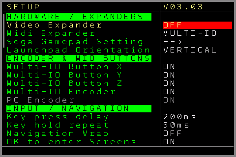
The different setup functions are split into main groups:
Hardware / Expanders
- Video Expander → Enables or disables the Video Expander functions. If no Video Expander is connected, this function should be turned off. If it is set to USB, the video functions are disabled, but a USB keyboard connected to the Video Expander can be used. If the setting is CLONE, the Video Expander is fully initialized and able to clone the NerdSEQ screen. By pressing OK with an enabled Video Expander, the Video (Hardware) Setup Screen can be entered.
If you press SHIFT+OK, the Video Expander will receive a reset signal. You might want to use this if your USB keyboard or HDMI output was not properly detected on startup.
- Midi Expander → Defines which Midi Expander is connected to the NerdSEQ. For the older Midi-IO with the Gamepad and for the TRS-A Midi Expander, choose DIN/TRS-A; otherwise choose the Multi-IO Midi & I2C Expander You may need to restart to be able to use all functions of the Multi-IO. This setting only has to be made once. Note that a Midi-IO or TRS-A Midi Expander will not work in Multi-IO settings and the other way around.
If you press SHIFT+OK, a connected Multi-IO Expander will be restarted. You might want to use this if its USB Device port doesn’t communicate reliably with the computer after reconnecting.
- Sega Gamepad Settings → Enters the Sega Gamepad Settings
- Launchpad Orientation → Defines how the grid of a connected Launchpad is laid out. HORIZONTAL runs the steps from left to right and then down to the next row, VERTICAL runs them from top to bottom and then on to the next column. See Launchpad Integration
Encoder & Multi-IO Buttons
- Multi-IO Button X → Turns the built-in function of the Multi-IO's X button on or off. OFF means the button still lights its LED when pressed but no longer selects the general purpose knob mode, leaving it free for the mappings (EXT → BUTN → MIOX).
- Multi-IO Button Y → The same for the Y button and the note entry mode (EXT → BUTN → MIOY).
- Multi-IO Button Z → The same for the Z button and the euclidean trigger mode (EXT → BUTN → MIOZ).
- Multi-IO Encoder → Switches the built-in function of the Multi-IO Edit encoder on or off. OFF means the knob no longer moves the cursor or edits notes and triggers and only feeds the mappings (EXT → MENC).
- PC Encoder → The same for the encoder (Volume + / Volume –) of a connected PC keyboard (EXT → PENC). With its function enabled the PC encoder follows the Multi-IO button modes just like the Multi-IO Edit knob does.
Input / Navigation
- Key Press Delay → Time until the key is repeated
- Key Hold Repeat → How fast a key is repeated (after the key press delay)
- Navigation Wrap → Enables/disables wrapping of the cursor when it reaches the beginning or end of a row/column
- OK to enter Screens → Enables automatically entering the pattern/patch/table when pressing OK on a pattern number on the sequencer screen/pattern screen.
- Edit Steps → Decides how many steps the cursor should jump down after entering a value using SHIFT + UP in the pattern screen. Value 0 turns the edit steps off.
Triggers
- Auto Fill-In Trigger → When enabled, a trigger of the default trigger type (see below) will be automatically inserted when inserting a new note
- Auto Remove Trigger → When enabled, the trigger will be removed when a note is removed.
- Default Trigger Type → Defines the trigger type that is used by several input modes (Euclidean, Launchpad ….)
- Trigger Delay Reach → Defines whether the trigger delay setting of the first 6 tracks should affect only the trigger column (Column) or all trigger commands and autogate (Full)
New Pattern Defaults
- New Pattern Length → Defines the default pattern length of a newly created pattern
- Default Groove Ticks → Defines the default groove for newly created patterns. (6 is the normal setting for a 24ppqn base)
Playback / Clock / Record
- Pattern Launch Type → Defines how patterns should be started/launched on the sequencer screen. The Setting ‘Normal’ is the standard setting where a newly selected pattern will start when the currently playing pattern has finished, regardless of its length and state (except when a new pattern is set to start on the next cue point).
If the setting is ‘Sync’, a new pattern is started at the zero cross of the mainclock. Shorter or longer patterns will keep on playing or switch to the next one on the chain if finished, but on the zero cross (or cue point if set to be started there) the newly selected pattern always starts in sync.
- Clock IN Auto Start → If you use MOD CLOCK (1/16 clock) or MOD-Clock 24 as the clock source and this setting is off, you need to start the sequencer yourself. If it is on, the sequencer will start automatically once a clock is received. It will stop the sequencer again after a timeout which can be set in the next setting:
- Clock IN Stop Timeout → If the previous setting is enabled, you can set the number of seconds without an incoming clock until the sequencer will be automatically stopped.
- Confirm Seq. Stop → Enables a confirmation before the sequencer is stopped with SHIFT+STOP.
- Reset FX on Seq stop → When enabled, Glide, Probability (Bitcrush, Distortion, Wavefold for Audio Tracks) effects will be automatically reset / turned off when the sequencer is stopped
- Play editing FX → If turned off, the FX value under the cursor (being edited) in patterns or tables will be skipped/not played. This avoids unintentional value changes while editing. If active, an ‘X’ is shown just below it in the pattern or table screen when the cursor is on an FX value, so you know this one is being skipped.
- Auto Gate on Note → Turn On/Off autogating. CV/Gate track: If a note is filled in on the pattern screen but no trigger, the Autogate function will automatically set the Gate with the note. The gate can be reset again with a Note Off. On note changes the gate will be low for a specified amount of micro/milliseconds until it will be set again. A value entered in the trigger column always overrides the autogate function. If it is turned off, no gate is generated automatically with a note; gates only come from the trigger columns or other sources.
- Auto Gate Timeout → If Autogate is turned on, this sets the time the gate is off until it goes on again between notes.
- Pre-Record Countdown → A count-in (like a metronome pre-roll) that plays before recording actually starts, so you can prepare before the first step is captured. The first number (change with SHIFT+CURSOR LEFT/RIGHT, OFF → 1 → 16) is the number of count-in beats (1 beat = 4 steps). The right part (change with SHIFT+CURSOR UP/DOWN) defines an additional optional beep sound on one of the audio outputs or a trigger on either the local or Trigger16 Triggers. When the recording is started with the internal clock, a countdown window appears which counts the beats down before the recording and the playback start. The record mode is armed on the last beat and the sequencer starts exactly when the countdown reaches zero. Press SHIFT+STOP to cancel the countdown, which brings you back to the previous screen and turns the record mode off again.
Files / Project
- Autoload last project → Loads the last saved project on the NerdSEQ startup automatically. You can prevent auto-loading by holding SHIFT when the NerdSEQ is starting up.
- Autosave Screensaver → Automatically saves the project right before the screensaver starts. It also makes a backup of the previously saved project, just as when you save a project manually.
- Backup folder → Show or hide the Backup folder in the Project Load filebrowser
- Sort Files A-Z → Turn on/off alphabetical sorting of the file lists in the file browsers. When OFF, the files are shown in the order the SD card returns them. If ON, the files are sorted alphabetically, which is a bit slower than the unsorted option (depending on the number of files).
Display / UI
- User Interface Setup → Set up your own colour scheme and change the font User Interface Screen
- Row Highlighting amount → Every X row in the pattern screen is highlighted (this setting is saved and loaded per project)
- Mainclock Progressbar → Shows the Mainclock steps and the cue-points either horizontally (classic) or vertically
- Show Decimal Values → Shows the decimal value for the most important hex values
- Default Note View → The default setting to show notes either as sharp (e.g. C#3) or flat (e.g. Db3). This setting can be overridden within the patterns.
- Pattern Scroll → Turns scrolling in patterns on/off. Scrolling is a nice visual gimmick but makes editing while playing very difficult.
- Screensaver → Here 4 different kinds of screensavers are available. Use SHIFT+CURSOR UP/DOWN to switch between screensavers (Waves, Lines, Arrows, Blank) and SHIFT+LEFT/RIGHT to select the number of minutes of inactivity (with the sequencer stopped) after which the screensaver starts. (Press OK to activate the screensaver directly, if not turned off.)
Maintenance / System
- Calibrate → Enters the Calibration screen to calibrate and test the NerdSEQ outputs
- Firmware Update/Reset → This option allows you to either reset / restart the NerdSEQ (not a factory reset) or to force entry into the bootloader screen for a NerdSEQ firmware update. Press OK to enter and you will get the options for a reset → press STOP; or the firmware update → keep SHIFT+COPY+CURSOR UP held; or to abort and get back to the Setup Screen → press LEFT. It will reset and enter the bootloader (keep holding the buttons, even if the bootloader shows an error message at first; it will try again). If a NERDSEQ.HEX is found in the firmware folder, the screen shows the instructions for the firmware update, otherwise it tells you that no update file was found while the reset is of course still available. A ‘Please wait’ window is shown while the reset is running. When the 20-second countdown has finished, it will return to the Setup Screen
- Expander Firmware update → Opens the Expander Firmware Update Screen for the expanders (NSA, Video or Multi-IO)
20
Sample, wave and synthesis
The Audio Tracks are capable of sample playback, waveform generation (oscillators) and generating synthesizer sounds (FM synthesis). Each of the four audio parts can be used for a different purpose, so sample playing, running oscillators and synthesizing can be used together. Every part has its own processing (Wavefolder, Bitcrush, Distortion) and mixing (Volume, Mute).
The final audio signals are routed through a (lo-fi) delay unit before they arrive at the Sample output jack on the front panel.
The audio signal after the volume process can further be used to Frequency Modulate one or more of the 4 oscillators/operators. This enables FM synthesis generation.
The pre-delay audio signal of audio track 7 can also be routed to overwrite the audio track 8 pre-delay part. This allows you to have the same audio on both the audio 7 and audio 8 outputs, and in combination with different delay settings for each, a nice stereo effect can be generated.
Every unit and part of the audio flow can be manually manipulated in the Track Setup or modulated through the Automators, envelopes and from the sequence.
Internal audio flow and routing:
Sample Playback
Any audio part can be used to play back any previously loaded samples. These can be pitched and manipulated from the sequencer. Samples are stored internally using an 8 bit or a 12 bit resolution (you choose that while loading the sample). 12 bit sounds clearly better, but it uses twice the memory. To get the best audio results and lowest conversion noise, samples should be normalized well before you use them with the NerdSEQ.
Samples can be looped in several ways (forward, pingpong and frame loops), played backwards and more. A looping sample can act like an oscillator. The loop start, loop end and loop/frame position are set per sample slot in the Load Sample window and can be modulated from the Mapping Screen. To gain more sample time (since it is limited to ~4 seconds / 180kB), you can choose to load samples at a lower sample rate, which might still be acceptable for your audio needs. You can of course also use this as an effect. Two samples can play at the same time per audio output / audio part.
Synthesis
Besides samples, each audio part contains its own oscillator / operator. Each oscillator can generate sine, triangle, ramp, sawtooth, pulse and noise. Once an oscillator is started, it keeps running until it is stopped, either with the note-off function in the sequencer, or a manual stop. You can also cut the volume to silence them or apply an envelope to the volume. 2 oscillators can be played at the same time on one audio output, since each track has 2 audio parts. These can be sequenced separately, or the sequenced notes can be cloned so both parts play exactly the same notes. The cloned 2nd oscillator notes can be detuned by either semitones/octaves or finely de-tuned to get a wider soundscape. Different waveforms are also possible here.
The pulse wave has an additional setting to change the pulse width.
Both oscillators (per track) can be hard-synced to each other. For each oscillator / wave, 3 processing effects are available: Wavefold, Bitcrush and Distortion. The Wavefolder is a triangle folder which keeps folding the signal back at higher drive settings instead of just flattening it out, so it keeps generating new harmonics even at extreme settings.
Each oscillator can also be Frequency Modulated by any other of the oscillators (or itself) and thus be used as an FM operator. By connecting multiple operators to each other, acting as modulators and carriers, a wide range of FM sounds can be generated.
For example, Operator 1 (carrier) can be modulated by Operators 2 and 3 (modulators), while Operator 3 can itself be modulated by Operator 1 or others. Many different 4-operator FM algorithms can be created in this way. The volume of the operator then acts as the ‘modulation index’. Note that the modulator signal used to modulate other operators is taken after the processing stages (Wavefold → Bitcrush → Distortion) and the volume process in the audio flow. This allows additional effects and variations for the modulations. Not only waves but also samples can be used as modulators (but not as carriers). The better normalized the sample, the stronger its effect on the modulation.
Operators can also be muted so you can’t hear them in the modulated signal.
The note cloning function can also be used for proper key tracking of the operators. Transposing / Detuning them adds new harmonics to the sound.
Nearly all parameters from all operators/oscillators can also be controlled by the Automators, envelopes or the sequencer.
Examples of generating typical FM synthesis:
- Go to the Track Setup
2-operator algorithm: operator 2 modulates operator 1, which sounds on audio output 7. - Choose Sample/Wave 1
- Set Modulation Source to FM OP2 (which means this operator is modulated by Operator 2)
- Choose Sample/Wave 2
- Set Muted to yes (otherwise you will hear the sound of oscillator/operator 2 on the audio output)
- Set Clone notes from to 1 (so the key is the same as that of Operator 1; this keeps things harmonic to start with)
- Make a sequence in the pattern screen while audio 1 is set to one of the waveforms (sine for the classic FM sounds)
- Play the sequence. Play around a bit with the Volume and the Clone coarse of Operator 2. OP2 will automatically start with a sine. This can of course be changed.
For now it is more of an FM oscillator. Let’s apply some envelopes to get a real FM synth voice:
- First you may want to set the volume of Operator 2 to a high value, because this makes the envelope more effective.
- Go to the Envelope screen (press the AUTOMATE button twice)
- Choose envelope 1. Set to ‘One Shot’ (for now).
- Set the Source to T7 Audio 1 (where each note on of track 7 audio 1 will trigger the envelope)
- Set the Destination to Volume 1 (which then acts as a VCA for Operator 1)
- Press the OK button so the source/destination will be activated
- Change the envelope settings so the envelope sounds nice with your sequence
- Choose envelope 2. Set to ‘One shot’ as well. Set source to ENV1 Start (so it will always be triggered when envelope 1 is triggered; there are multiple ways to have it triggered by the first sample/wave/audio).
- Set the destination to Volume 2 (which then also acts as a VCA for Operator 2. The effect is that it defines the ‘modulation index’ or the ‘deepness’ of the modulation).
- Change the envelope parameters so they match the first envelope nicely
- To create more percussive sounds, you can set envelope 2 destination to Pitch 2.
The audio can be heard from audio/sample output 7. Since only 2 operators are used, you could add a 2nd version of it, the same with operator 3 and 4 (with its own envelopes). This will then output on sample/audio output 8. If you want both to come from one audio output, build this algorithm with operator 1+3 and Operators 2 + 4 instead. Turn off the mute of operator 2 and you will have a duophonic 2 operator synth on one audio output.
- Choose Sample/Wave 1 and set Modulation Source to FM OP2+4 (which means Operator 1 is modulated by Operators 2 and 4)
- Choose Sample/Wave 2 and set Modulation Source to FM OP 3
- Mute Sample/Wave 4 if you don’t want to hear it from audio output 8
- Set Clone notes to 1 on operators 2,3 and 4
(of course you don’t have to clone the notes from operator 1, but you would need to add an extra sequence for these non-cloned operators to achieve sequenced FM, which is really great for cool FM sounds, effects and music).
- Again, apply envelopes as needed.
If you clone the notes, nice additional variations can be created by using different ‘Clone coarse’ and ‘Clone fine’ settings.
Many different algorithms can be employed like this. Feeding operators back into the chain can generate nice unexpected results. Using the FM boost setting will create stronger FM sounds.
Keep in mind that when building algorithms, the audio from operators 1 + 2 will always be audible on audio output 7 and operators 3 + 4 on output 8 (unless muted).
This is visualized in the following algorithm where 3 operators are routed directly to the audio output. Since operators 1+2 sound on audio output 7 here and Operator 3 on audio output 8, you would need an external mixer to mix audio outputs 7+8.
Delay
Each audio track also has a delay unit (echo) as a last stage before the audio output.
The delay is a lo-fi delay implementation with 4 different timing possibilities:
- Short HQ → best quality but very short delay
- Lofi → lower quality, lower sampling rate but longer delay time
- More Lofi → lowest quality and sampling rate, but longest delay time
- Fast → Good quality, very short time (flanger kind of effect)
Additional delay parameters are:
- Delay time (where 0 is the shortest and 255 is the longest)
- Delay send → The volume of the input (and so output) signal into the delay unit
- Delay feedback → The intensity of the feedback into the delay unit. A setting of 15 means there is no loss in the volume and the delay signal stays in the delay-loop at full volume.
Note that because of the nature of the delay implementation (the delay time setting changes the size of the delay buffer) a change in the delay time can create audible artefacts, caused by old delay data in the delay buffer.
The delay settings can be changed in the Track Setup for audio 7 and 8 or through the sequencer FX command.
Both audio outputs can have different delay settings and by cloning audio 7 to 8, you can create a nice stereo delay effect if these delay settings are only slightly different. Use audio output 7 for the left and output 8 for the right channel (or the other way around, of course).
All current settings are saved and loaded with the project.
21
Load Sample window
The Load Sample window can be accessed from either the Project screen or from the Nerd Menu on a sample track or in a sample pattern. It is used to add samples to the 12 sample slots.
Supported sample formats are:
- RAW 8bit unsigned
- WAV wave files in 8, 16, 24 or 32 bit as PCM or floating point wave types.
Use the cursor up/down to navigate between the 12 slots. Press OK on one slot to open the file browser and choose a sample, press OK again to load the selected file into the slot. If there is not enough memory available, it will offer a choice to load the samples at a lower sample rate, which uses less memory. This also happens when sample memory is too fragmented. Repeatedly loading, reloading, and deleting samples within one session can cause fragmentation. Given the limited memory, the embedded environment, and the real-time aspect (you may want to load samples while the sequencer is playing), defragmenting samples in real time is very tricky. For now, in most cases it will simply refuse to load the sample in that situation.
However, when powering on or loading/reloading the project, the sample memory is automatically de-fragmented. The same applies when loading a sample block: the loaded data is de-fragmented.
You can also force resampling by loading the sample with SHIFT+OK. This will open the resample choice, which gives you the option to load samples at lower sample rates (44100, 22050, 11025, 5512, 2756 Hz). You also get the choice to interpolate a sample (SHIFT+OK on the selected sample rate), which can give a different result when reducing the sample rate. Samples loaded with a different sample rate will also have a different base-octave.
In the resample window you also choose the resolution the sample should be stored with. Use CURSOR LEFT/RIGHT to switch between ‘8 Bit’ and ‘12 Bit’. The sizes in the list are updated immediately since a 12 bit sample uses twice the memory of the same sample in 8 bit. 12 bit only makes sense for wave files that really carry more than 8 bits (16, 24, 32 bit and floating point). A RAW file or an 8 bit wave file is always loaded as 8 bit.
Since the resolution is chosen in the resample window, you load a sample with SHIFT+OK if you want to load it in 12 bit quality. In the sample slot list a 12 bit sample is marked with a ‘*’ in the HQ column.
Samples in projects that have been saved with a firmware older than V3.03 are always loaded as 8 bit. Load the wave file again if you want to use the 12 bit quality for them.
Good to know: A 12 bit sample uses twice the memory of an 8 bit sample, which also means less overall sample time. However, in tests it turned out that a 12 bit sample with 22kHz sounds much cleaner than the same sample in 8 bit at 44kHz.
Samples can be pre-listened by pressing SHIFT+LEFT (audio output 7) or SHIFT+RIGHT (audio output 8) in the file browser. The sample will keep playing as long as you hold the SHIFT button. A pre-listen action halts all other samples playing on that audio track. However, the sequencer can run while pre-listening. By using SHIFT+UP/DOWN, the selected octave can be changed for pre-listening. While pre-listening in the file-browser, a note symbol is shown on screen.
Each sample slot has a set of loop functions: No Loop, Forward Loop, Pingpong Loop, Frame (no loop), Frame Forward Loop and Frame Pingpong. The frame variants loop a short window of the sample. A looping sample can also be set to OSC mode so it keeps looping like an oscillator (and keeps running also when the track or the sequencer is stopped). You can see the loop settings in the lower half of the screen. To get to the loop settings, press either the DOWN or the CURSOR RIGHT button. There you can change the loop settings, the start and end position of the loop/frame, and whether the sample should run like an oscillator. The loop positions can also be manipulated from the mappings which allows some granular and dynamic sample/oscillator effects.
The UP button or just moving up will bring you back to the sample slot selection.
SHIFT+DELETE will clear the selected sample slot and free its memory.
Below is the sample-slot window with 4 loaded slots:
- Abort
- HQ (high quality) flag
- Free sample memory
- Sample size
- Waveform preview
- Start and end point
- Loop mode
- Preview playback
- Selected slot
- Sample name
- Empty slot
22
Nerd screen / menu
The Nerd button opens a special function menu. Depending on the current cursor position, the screen (e.g. Sequencer or Pattern) and whether a block is marked, different choices are available to manipulate the selection.
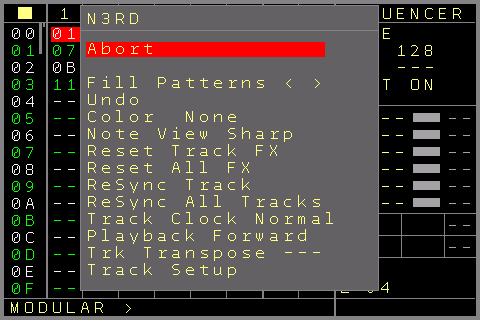
The following functions are available in the sequencer screen
If nothing is marked:
- Fill Patterns → OK Opens the Fill Pattern Screen to automatically fill a pattern using a set of rules. SHIFT+OK or SHIFT+CURSOR LEFT fills immediately with the regular fill settings without leaving the Nerd Menu. The same applies to SHIFT+CURSOR RIGHT, which does a Magic Fill (randomly generated fill settings). CURSOR LEFT alone (regular fill) or CURSOR RIGHT alone (magic fill) fills and returns to the sequencer screen. The fill is executed on the currently selected pattern. If no pattern is selected, a new pattern is created.
- Undo → The latest change in the sequencer screen can be undone so if you accidentally deleted something, it can be recovered. Keep in mind that only the last edit can be undone.
- Color → Sets the background color of the current cursor point. Change the color using SHIFT+CURSOR LEFT/RIGHT
- Note View → Sharp/Flat note view for the selected track
- Reset Track FX → Resets all FX / Current values of the tracks
- Reset All FX → Resets all FX / Current values of all tracks
- Resync Track → Resynchronizes the track to the mainclock on the clock zero crossing
- Resync All → Resynchronizes all tracks to the mainclock on the clock zero crossing
- Track Clock → Change clock dividers or multipliers of the track. If the player is playing, the changes are applied at the end of the pattern. If it is not playing, the changes are applied immediately.
Press SHIFT+OK to apply the new clock selection immediately (this might result in an out-of-sync pattern). Change using SHIFT+CURSOR LEFT/RIGHT. By pressing SHIFT+OK on the menu setting, the new clock setting will be activated immediately. The clock will then be changed from the current stage on and not synchronized to the mainclock or patterns. If a track is decoupled from the mainclock by setting the Track Clock to ‘Mapping’, the value can’t be changed here, only in the Track Setup Screen of the track. Conversely, if you want to set the Track Clock to ‘Mapping’, you have to use the Track Setup Screen of the track. - Playback → Changes the playback order of the track. Changing the value using SHIFT+LEFT/RIGHT will activate it after the pattern is finished. Press OK to activate the new order directly. You can create a new pattern from the selected playback order by pressing SHIFT+OK.
For more information about the available playback orders, see the CBPB FX function. - Track Transpose → Changes the current transpose of the track. (± semitones). The transpose only works if track transposing is allowed in the Track Setup Screen
Change using SHIFT+CURSOR LEFT/RIGHT/UP/DOWN
- Track Setup → Enters the track setup screen for the current track. (see Track Setup Screen)
If an area or field is marked:
- Fill Patterns → Same as with the unmarked fill patterns but the marked sequencer area is filled instead. Empty spots in the marked area create new patterns, which are then filled as well.
- Color → Sets the color of the marked area. Change the color using SHIFT+CURSOR LEFT/RIGHT
- Transpose Notes +1 → Transposes the notes (CV and MOD) in the pattern up by one semitone.
- Transpose Notes -1 → Transposes the notes (CV and MOD) in the pattern down by one semitone.
- Transpose Notes +12 → Transposes the notes (CV and MOD) in the pattern up by one octave.
- Transpose Notes -12 → Transposes the notes (CV and MOD) in the pattern down by one octave.
- Clock → Change clock dividers or multipliers of the marked tracks. It has the same functionality as when nothing is marked (see above).
The functions in the pattern screen
If nothing is marked:
- Fill Patterns → Same as the marked and unmarked fill pattern command for the sequencer screen. The current pattern will be used for the fill.
- Undo → The last change in the pattern screen (this pattern, not from others) will be reverted.
- Reset Track FX → Resets all FX / Current values of the track
- Playback → Same functionality as the Playback function in the sequencer Nerd Menu.
- Stop all Sound → Stops all sounds/gates, Midi and modulators of the current track. When pressed while holding SHIFT, all sounds of all tracks are stopped.
- Edit Pattern Name → Opens a text editor to add/change the name of the current pattern
- Pattern Length → Sets the length of the current pattern between 1..64 steps. The sequencer will play the pattern only for the selected number of steps. All jump and random jump functions will also stay within the selected length. SHIFT + CURSOR LEFT/RIGHT will increase/decrease by 1 step and SHIFT+CURSOR UP/DOWN will browse between these standard step counts: 64, 32, 16, 8, 4, 2, 1.
As you can change this value while the sequencer plays, it is possible to get ‘out of sync’ for the current track when changing the length. You can press the OK button to re-synchronize the track directly to the mainclock. Also changing the length while holding the OK button will directly re-synchronise the track while changing the length. Use this to create nice drum/synth fills in your live set.
This currently only works well with regular groove settings and if there is no clock scale running on the track.A default pattern length for new patterns can be set up in the Setup menu.
- Track Setup → Enters the Track Setup Screen for the current track
- Export Pattern → Choose to export the current Pattern onto the SD card. The file menu appears with the current pattern number and name (if a pattern name is available). The name can be edited further, and by selecting ‘ready’ the pattern is saved to the SD card (project folder). The project name and pattern type are added as well.
- Import Pattern → Choose to import a Pattern from the SD Card. Using a file browser, a previously exported pattern can be imported into the current Project. An imported Pattern will be imported into a new empty pattern. The new Pattern number will be shown after importing and can be used in tracks with the same pattern type.
If a pattern block is marked:
- Fill Patterns → The same fill function as with the unmarked pattern but only the marked parts will be filled. Also the marked parts are pre-selected in the Fill Pattern Screen (e.g. Notes + Triggers).
- Transpose +1 → Transposes the marked notes one semitone up
- Transpose -1 → Transposes the marked notes one semitone down
- Transpose +12 → Transposes the marked notes one octave up
- Transpose -12 → Transposes the marked notes one octave down
- Shift Up/Down → SHIFT + CURSOR UP/DOWN shifts the marked parts up and down, with wrap-around.
- Flip Rows → Flips the order of the marked parts around, up is down and down is up
- Randomize order rows → Randomizes the order of the marked parts.
The nerd-menu functions for a table screen
- Preset xxxx → Insert presets into a table
- Edit Table name → Opens a text editor to add/change the name of the current table
- Release Table → Erases and empties the current table so it can be reused.
See the Table Screen part of the manual for more details on the Nerd Menu functions in the table screen
The nerd-menu functions for a patch screen
- Edit Patch name → Opens a text editor to add/change the name of the current patch
The nerd-menu functions for a mapping screen
- Threshold → Sets a threshold value which can be used to compare against in the mappings using the CALC or SKIP functions.
- Export Mapping → Export a mapping to the SD card.
- Import Mapping → Import a mapping from the SD card.
These 2 functions allow you to save and load the complete set of mappings. You can define the name of the saved file. Mappings will be saved in the regular project folder.
This is a nice feature, as users can create mappings on request, share their mapping work or re-use special mapping templates.
- Export Part → If a block is marked on the mapping screen the export entry shows ‘Export Part’ and only the marked rows are exported, into a NAME_PART.MAP file. Importing such a file inserts the rows at the cursor position. See Mapping Screen for the details.
- Note View → Sharp/Flat note view in the mappings.
- Stop on Edit → If enabled, the mapping will automatically pause while any destination parameter in the mappings is being edited.
The nerd-menu functions for the scale screen
- Note View → Sharp/Flat note view in the scale screen
23
Fill Pattern screen
The Fill Pattern screen generates a complete pattern (or a part of it) automatically, based on a set of rules you define. It is a fast way to create a starting point, add variation or fill in drums, notes and modulations without entering everything by hand. The fill pattern option is available for all track types (except for the Video Tracks which don’t have any note, trigger or pitch data).
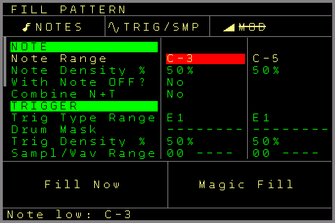
You reach the Fill Pattern screen from the Nerd Screen / Menu.
The screen is split into three zones:
Top → three master toggles which decide what is filled: Notes, Triggers and Mod. Notes and Triggers are simply on or off. Mod has three states: Off, Pitch (fills the MOD/pitch values) or Notes (fills note values into the mod columns). Only the groups whose toggle is on will be written.
Middle → the parameter rows, grouped into the sections NOTE, TRIGGER, MOD and GLOBAL. Each row has a Min and (where useful) a Max value, so most settings define a range from which a random value is picked. Min/max can simply define a range, but it can also be used, for example, to have lower notes in the earlier steps and higher notes in the later steps (or the other way around); the same applies to density etc.
The available parameters are:
NOTE SECTION:
Note Range → the range of notes that can be used for the fill. Starting from an empty field (—) to C-0 → C-A and the 16 notes generated by the random ranges.
Note Density → the percentage of rows that will receive a note.
With Note OFF? → also place note-off commands. These will be randomly chosen instead of a Note.
Combine Note + Trigger → couples notes and triggers so they are placed together on the same steps.
TRIGGER SECTION:
Trig Type (Min/Max) → the range of trigger types that can be placed. This goes from an empty spot up to FE. It uses the regular Trigger commands of a trigger column.
Drum Mask → which of the 16 drum-matrix columns may be filled (Min selects columns 1-8, Max selects 9-16).
Trigger Density → the percentage of rows that will receive a trigger.
Sampl/Wav Range → for audio tracks, the range of sample/waveform slots to choose from.
MOD SECTION:
Note/Pitch Range → the range of MOD values. Depending on the Mod master state these are pitch values (000-FFF) or notes.
MOD Density → the percentage of rows that will receive a mod value.
Volume Range → for audio tracks, the range of the sample/waveform volume.
Velocity Range → for Midi tracks, the range of velocity. Both the Min and the Max value can also continue into the Midi slide settings.
The sections also include the Sample/Wave range and Volume Range (for audio tracks) and the Velocity Range (for Midi tracks), so they match the 2 or 3 separate columns within a pattern.
GENERAL SECTION:
Scale → quantizes the placed notes to a scale: No scale, the Global scale or one of the 90 scales, together with a base key.
Interval → how the placed steps are spread out:
- Density → random, using the density values defined in the other sections
- Every X steps → Only every X step is filled in.
- Euclidean → Fills the steps with the euclidean method
- Block → Fills in fixed step blocks. If, for example, you choose a value of 3, 3 steps in a row will be filled, followed by 3 empty steps, followed by 3 steps filled etc.
Range Direction → how values are taken from a range:
- Ascending → Fills linearly from low to high, for example a MOD column from 000 → FFF depending on the range settings
- Descending → Fills linearly from high to low
- Random → Fills by selecting a random value within the range
- Triangle → Fills linearly ascending for half of the fill and then descending for the rest
- Sine → Fills the rows like a sine curve within the range
Fill Behaviour → How the values are filled in:
- Overdub → Add on top of existing content
- Only — → Only write to empty fields
- Clear & fill → clears the pattern first
Fill Offset → shifts the filled result by a number of steps. Useful for the euclidean, every X steps and block intervals
Fill Columns → for tracks with several note/mod columns, selects which of the 6 possible columns are filled (column 1 is always on).
Remove % → after filling, randomly empties this percentage of the placed fields again. A handy way to thin out a result that came out too busy. Useful as well for overdub fills.
New Pat Length → If a new pattern is created (fill into an empty spot from the sequencer screen), it will get the selected pattern length.
If you use different percentages for the min and max of the density settings, the Range Direction (ascending/descending/triangle/sine) also applies to the density per row. For example, with ascending, the first steps are less populated and later steps more populated.
At the bottom of the screen are the fill execute options:
- Fill Now → fills the pattern using all the settings above.
- Magic Fill → a quick randomised fill which applies its own rules for an instant result.
Nearly all fields get randomised values, except for the following, which use the normal fill values: the Notes, Trig and Mod toggles (so you can select what should be filled), Trig type range, Drum Mask, Sampl/Wav range, Fill Behaviour, Fill Columns, New Pattern Length and Remove %. Also some ranges are clamped between 20 and 80%. Tests showed that if these settings were also chosen completely at random, the fills would very often be useless (e.g. empty patterns 90% of the time, or completely filled patterns with trigger chaos where most notes would stay on).
A magic fill will not alter the regular fill settings.
Pressing OK will fill and return to the pattern / sequencer screen. SHIFT+OK will fill but stay in the Fill Pattern screen.
The Fill function can also be triggered live from a pattern using the SPFX commands or from the Mapping Screen, so a pattern can refill itself or be refilled while playing. The fill settings can also be changed by mapping screen destinations, so you can manipulate and control fill results live.
24
CV Input / Gamepad screen
The NerdSEQ has recording facilities with flexible recording sources as well as live manipulations through the CV/Gate inputs. Recording is step-based, so only values for each step are recorded. (For motion ‘CV’ recording you would use the Automator LFO (Automator Record) which got a dedicated motion record mode. The necessary parameters can be set up in the Project screen → CV Input/Gamepad
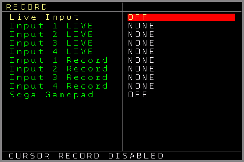
The recording / live input screen is split into 3 main parts.
Live Input with the 1..4 Input definitions → Assign the CV inputs to manipulate several destinations live.
5 menu items are available here:
- Live Input ON/OFF → Enables general live input for the CV inputs. If turned OFF, the live input and thus the assigned CV input parameters are disabled.
- Input 1..4 → While the CV inputs are the sources (0..10 Volt for CV and 0..5 Volt for Gates/triggers), the destinations can be set on the right side.
Possible Destinations are:Transpose T1…T8 → Transposes the CV outputs of tracks 1..8 live while the CV input is quantized to note scaling. The middle point for the transposition is C-5 (5 Volt input), which means no transposition. Voltages below will transpose the output down and voltages over 5 Volt will transpose up. Note that transpose must be allowed (track settings) for this to take effect on the tracks.
Transpose All → same as track transpose, but it affects all tracks together (only tracks that allow transposing)
Pass to CV, MOD, TRIGGER 1..6 → The voltage of the CV input is passed to (and overwrites) the CV or MOD output. If a trigger is set up as the destination, a threshold will determine either Trigger On or Trigger Off. Please note that the passthrough is updated with every change of the input, so the outputs are also updated, which will overwrite a currently playing sequence.
Quantize to CV, MOD, TRIGGER 1..6 → The voltage of the CV input is quantized to note scaling and output to the destinations CV 1..6 or MOD 1..6. Only a change of the note will be passed through to the output. If a trigger is set up as the destination, a threshold will determine either a Trigger ON or a Trigger OFF.
Position X/Y/Start/Stop → ‘Etch A Sketch’ moving of the cursor in the sequencer screen.
‘Position X’ moves the cursor in the sequencer screen horizontally between the Tracks 1..8. The lowest CV value will position the cursor on Track 1, while the highest CV value will position it on Track 8, with everything else linearly in between.
‘Position Y’ moves the cursor vertically between the rows on the sequencer screen. The lowest CV values will position the cursor on Row 00 while the highest CV values will position the cursor on row FE. Other voltages are mapped linearly to the rows in between.
‘Position Start’ A trigger / gate on the CV input starts the pattern at the cursor position next.
‘Position Stop’ A trigger / gate on the CV input initiates a stop of the track/pattern on the cursor position.
Audio 7..8 Gate / Trigger → Plays the last set/used sample on Track 7..8 while the gate is set or, if set to trigger, triggers the sample.
Audio 7..8 Pitch → Defines the note of the sample which is played through the Sample/Gate function.
Audio 7..8 Offset → Defines the start/offset position of the sample which is played through the Sample/Gate function (can be used to start different slices of the sample).
Audio 7..8 Slot → Defines the sample slot which is played through the Sample/Gate function. If not defined, the last played sample will play.
As explained earlier, if Live Input is turned off, the input settings have no effect.
Destination types can be changed using SHIFT+CURSOR LEFT/RIGHT and destination numbers (e.g. tracks 1..8) can be changed using SHIFT+CURSOR UP/DOWN.
Input 1..4 Recording → Assign the CV inputs for recording
CV 1..6 Note → Records a note into the currently playing step. Records only if in record mode and a pattern is playing on the track of the selected CV. The notes are filled in on change.
MOD 1..6 → Records a modulation value into the currently playing step. Records only if in record mode and a pattern is playing on the track of the selected MOD. Modulation values are entered on any change in voltage detected.
GATE 1..6 → Records gates into the trigger column at the currently playing step. FE for Gate ON and 00 for Gate OFF. Records only if in record mode and a pattern is playing on the track of the selected Gate.
TRIGGER 1..6 → Records triggers into the trigger column at the currently playing step. Fills in a the default trigger value if a trigger happened on the CV input.
CV NOTE + GATE 1..6 → Records CV notes + gates into the currently playing step. It only fills in a note when a new gate occurs. This option always uses 2 inputs, so the CV input below the current one is automatically chosen as the gate input. Additionally, the gate input detection can be delayed, so sources with a slew on the CV (where the CV value is not yet stable when the gate arrives) can also be recorded well.
The delay value can be changed below the input setting.
This is the best choice if you want to record CV + Gate from a source like a keyboard.
It can only be used on the Input settings 1,2 and 3, as it always needs 2 inputs.
CV NOTE + TRIGGER 1..6 → Same as CV NOTE + GATE 1..6, except that triggers are detected and recorded.
CURSOR CV → In combination withCURSOR GATE on another input. Records a note at the current cursor position. In the pattern screen, it places a note in the Note column when a new gate occurs at the current cursor position. A Gate On (FE in the Trigger column) is added, too. If the gate is released on the same step, the Gate On is replaced by a trigger of 40. The cursor can be moved to another step, and if the gate is released there, a gate off (trigger column 00) is filled in.
If the gate is held for more than 1 second on the same step, the note and the trigger value of the cursor will be deleted.
The sequencer doesn’t have to play or be in record mode. Edit Mode must be enabled though for it to work.
This allows editing notes in the pattern screen from a CV/Gate keyboard.
SAMPLE PITCH 7..8 → Selects the sample / note that should be recorded.
SAMPLE SLOT 7..8 → Selects the sample slot that should be used for a sample note record.
SAMPLE GATE 7..8 → Records notes (defined by SAMPLE PITCH) with the selected Sample slot (defined by SAMPLE SLOT) into the currently playing step. Records only if in record mode when a pattern is playing on the selected sample track. It only fills in a note when a new gate occurs. If no slot is selected, the last slot is used.
Gamepad Record → Enable/Disable the recording of the assigned gamepad pads. The recording buttons can be assigned in the SETUPSega Gamepad Settings. (Set button to Gate 1..6 or Trigger 1..6 record)
Once the recording sources/destinations are set up, you can press SHIFT+RECORD to enable recording. The selected pattern will start to play (possibly after a record pre-roll) with recording enabled at the same time. You can then also start other patterns to be included in the recording, OR start the patterns first and press SHIFT+RECORD afterwards when you want to start recording.
SHIFT+RECORD will stop the recording while the pattern keeps playing. Stopping the sequencer (SHIFT+STOP) will also turn recording off.
Recorded values will be directly routed to the corresponding outputs as well. So a kind of looped recording/playing is possible.
In Record mode, values can be deleted ‘on the fly’ by pressing and holding the TABLE (Record without shift) button while in the pattern screen. Any notes that are played while holding TABLE will be deleted from the currently playing sequencer step.
If the cursor is on the trigger column of a CV/Gate track in a playing/recording pattern, triggers can be ‘tapped’ in using the OK button.
25
Midi / I2C Setup screen
The Midi / I2C Setup screen contains a range of Midi and I2C settings to customise and set up the Midi and I2C ports. At the top of the screen you can see if the Multi-IO or one of the other Midi-Expanders is selected. It will show the Multi-IO Firmware Version if you have a Multi-IO Expander connected and enabled. With the Multi-IO, you can also see the USB-Host firmware at the bottom in the status bar. The Multi-IO contains 2 different firmwares, for the main part and the USB-Host part. Please check the website for new firmware versions.
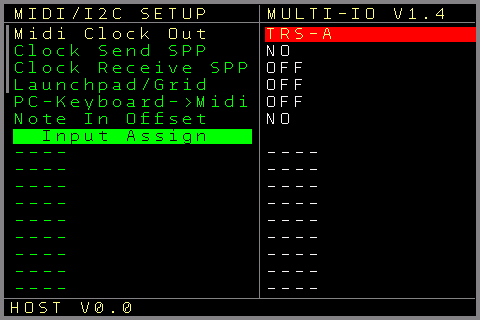
Settings of the Midi / I2C Setup Screen:
Midi Clock Out → Defines whether and which Midi ports send out the Start/Stop and Clock Transport commands. The settings are: TRS-A(DIN), Host, Device, TRS+Host, TRS+Device, Host+Device, TRS+Host+Device
Clock Send SPP → Defines whether the Song Position Pointer (SPP) should also be sent on sequencer start together with the clock data. Please disable it if the Midi followers are not capable of processing SPP data. This setting is disabled if no Midi clock output is selected.
Clock Receive SPP → Defines whether the NerdSEQ should act on received SPP messages. It can move the playing sequence to a bar etc. defined by the leading Midi device. For example, a DAW could play a pattern or a bar in a loop, and the NerdSEQ would play the same loop at the same position. Disable it if it is not being used. You can enable this setting only if the NerdSEQ is set up as a Midi Clock follower.
Launchpad/Grid → Enable the different Launchpad types (currently only Novation Launchpads are supported) for a NerdSEQ integration. See → Launchpad Integration
The different Launchpad versions (LP Mini, LP MK2, Pro / MK3 / X) can be selected to be controlled via one of the Midi ports (TRS/DIN, USB-Host, USB-Device). Note that you might need a USB-Host converter if you are not using the USB-Host on the Multi-IO Expander. The Launchpad PRO/MK3/X has 2 modes to select from. One without the * in the name (e.g. PRO MK3-HOST), where you have to enable Programmer Mode on the Launchpad manually (usually by holding the Setup button for a second and pressing the orange button on the Launchpad; otherwise refer to your Launchpad manual).
The one with the * (eg PRO MK3-Host*) will automatically initialize the Launchpad in Programmer Mode (tested with several Launchpad devices). Be aware that this setting can’t be disabled on the Launchpad itself. To disable it, navigate to the setting without a * on the NerdSEQ and press the OK button. This is a Novation function which locks the Launchpad to the external device settings.
PC-Keyboard → Midi → Routes the PC Keyboard into a Midi Input which can be selected as a Midi source (See Input assign below). The PC keyboard then acts as a simple Midi note keyboard and can play, record or transpose tracks just like an external Midi keyboard.
Note IN Offset → As the Midi standard is pretty vague about which frequency, for example, a C in octave 3 should have, and different manufacturers use different octave offsets, this setting can be used to flexibly change the Midi note input offset, so the octaves always match well, regardless of the Midi input device. The setting can have a positive and negative offset.
Input Assign → Here you can have up to 16 different settings where you can connect different actions to selected Midi Input Channels/Ports.
On the left side (change with SHIFT+CURSOR UP/DOWN) you can select the different Sources. Holding the OK button on an empty spot (—-) activates the Learn function, and the next received Midi Message will automatically fill in the received Midi Port and Channel. You can also fill in the port/channel manually which also allows additional input types: Starting with the TRS/DIN Midi input Channels 1-16, if a Multi-IO is enabled then Host Input Channels 1-16 and Device Input Channels 1-16. Next are TRS, Host and Device All Channels, and All Midi, which accepts input from all Midi channels. Lastly, you can select Mapping as a source. With that you are able to record or play any mapping data (selected by the mapping destination GLOB→MREC = Global→ Row as Midi Record Source). Currently only the MOD column of a Modular Track is able to record/play the mapping data. You need to define which mapping row should be the record/play input in the Track Setup of a Modular Track (Midi → MOD function to any of the mapping rows which contains the GLOB-MREC destination). This would allow you, for example, to record only the aftertouch information into the MOD column and much more.
On the right side you select the Destination for the Midi Data (change with SHIFT+CURSOR LEFT/RIGHT). The following destinations are available:
- Transpose All → Selects the global transpose while Midi Note 60 means no transpose. Higher and lower values will transpose up or down relative to note 60.
- Track Select Record → With this, the recording destination is chosen dynamically, depending on which track is selected (the track column the cursor is on in the sequencer screen). This works in all screens, and the last selected track is used.
- Step Input → (replaces the former Midi Step Channel setting)
It is used to edit notes directly in the pattern screens. To use it, the cursor must be on the note column of the pattern screen. Playing a note (for example on a Midi keyboard) will insert a note at the cursor position. If the note is released on the same step as the note on, a trigger (KILL for Midi tracks) is inserted for a short note. If the note is released on another step, a note off is inserted. Holding the note for more than 1 second will remove the note at the cursor position.
The sequencer doesn’t have to play or be in record mode. Edit Mode must be enabled though for it to work. This allows you to edit notes in the pattern screen from a Midi keyboard. Be aware that this is not the regular record mode for Midi input. Also, if this is enabled together with the regular recording settings of the track, double notes might appear.Start/Jump Row → Will launch a row defined by the Midi Note. Rows 0-78 (120) are supported by the 120 possible Midi notes. The velocity controls how the row is launched. A velocity < 64 will cue the selected row to be launched; pressing it again toggles it so it can be launched at the cue points.
A velocity > 64 executes the Jump function, so the playback jumps directly to the selected sequencer row, continuing at the currently playing step in the newly selected pattern. (Same as the OK Button if Edit Mode is disabled). If your Midi controller supports it, you can define which functionality it should send out on a button press.Mute/Solo → Will Mute/Solo the tracks where the function and track can be defined by the note and velocity. Note 48 – 55 will define the Track and a Velocity < 64 will Mute the Track while a velocity greater than 64 will unmute the track.
Note 60 – 67 will define the Track again and a Velocity < 64 will Solo the Track while a velocity greater than 64 will unsolo the track.
Merge to TRS → Merges the source data to be sent out of the TRS port. This is a kind of thru function, but keep in mind that it is a software thru and will not pass all Midi data to the destination. This also applies to the next 2 destinations.
Merge to Host → Merges the source data to be sent out of the USB-Host port. Merge to Device → Merges the source data to be sent out of the USB Device port.
TRACK 1..8 Input → Use the source to play a track (like a Midi→CV converter). Notes are routed to the CV note, Note On/Off go to the trigger output On/Off, and the modulation wheel, Velocity or a Mapping Destination result is routed to the MOD output (if defined in the Track setup) on a modular track. Pitch bend bends the pitch of the destination track if possible.
For Midi tracks, the Midi data is passed through to the track’s Midi channel.
For Trigger16 Tracks, all 16 Trigger outputs can be played through Midi notes, starting from note C-3. NOTE ON sets the Trigger and NOTE OFF resets the Trigger output. The next 8 notes will trigger the selected 8 Trigger Columns (either 1..8 or 9..16). From note C-5 the trigger outputs behave as triggers instead of a gate, so a note off will have no functionality.
For audio Tracks, the sample is played on NOTE ON and stopped on NOTE OFF. The volume is defined by the velocity. Additionally, the sample slot being played can be changed through the program change Midi command (0..11 for the 12 slots). For a CV16 and I2C track the Midi input is used to play into the 6 Note Columns.
TRACK 1..8 Record → Live records into the destination tracks. Note on fills in a note on the current recording step. If the note is released on the same step, an F0 is filled into the trigger column. If the note is released on another step, a note off is inserted.
For audio tracks, the note is filled in and the velocity defines the sample volume. The last used sample slot is used for recording; the sample slot can be changed by using a program change command.
For Trigger16 tracks, triggers can be directly recorded into the drum-matrix. Starting from note C-3 all 16 drum-matrix values can be inserted with a note on command.
For CV16 tracks, up to 6 voices can be recorded at the same time or, if set up that way, up to 5 voices plus a dedicated envelope. The type of recording is set up in the CV16 Setup screen.
For Midi Tracks, polyphonic Midi recording is possible. Up to 4 notes at the same time can be recorded as well as all Midi parameters like Program Change, Midi CC, Pitchbend, Aftertouch… Keep in mind that Midi data will only be recorded as long as there is space in the FX columns. If all 3 FX columns are already filled in, the additional data is ignored for this step.
TRACK 1..8 Transpose → Transposes the destination track (quantized to notes). Note C-4 is the middle position, which means no transposition. Higher notes transpose up and lower notes transpose the destination down. Be aware that the transpose only works if track transpose is allowed for the destination tracks.
User Harmonic 1..4 → Feeds incoming Midi notes into the allowed notes of scale 5A (a live 'scale lock'): the held notes set the harmonics and stay latched after the keys are released. Newly pressed Midi notes will create a new (harmonic) scale.
Table 00..1F Arp → Feeds incoming Midi notes into a selected table (00-1F) to build table arpeggios automatically. The pressed keys are written into the table transpose column, so a chord played on a keyboard turns into a running table arpeggio. Midi Note C-5 (Note number 60) is the middle note which results in no transposition, while higher and lower notes cause positive and negative transpositions.
Next are the record/input filters. They allow incoming Midi data to be filtered out to avoid recording unneeded Midi data. The following filters can be enabled/disabled:
Velocity (will only fill in 127 or 0 if disabled), Polyphonic Aftertouch, Channel Pressure/Aftertouch, Program Change, Pitchbend, CC Controller Data.
If Midi is enabled, a little information about the incoming Midi data will be shown at the bottom of the screen. It shows whether a Note On or Note Off command, or a Midi CC with its controller number, is being received on the channel. This can be used to check whether the input works in general.
Next are the basic I2C port settings, which define the 2 I2C port modes on the Multi-IO Expander. These are like physical settings, since an I2C port can be either leader or follower (i.e. output or input). The 2 I2C ports are named A and B, and each can be set to the following modes:
Off → (decouples the port so it is invisible on the bus)
First the follower modes:
16n → NS 1-16 → Enables the use of a 16n faderbank (any 16n-like faderbank, as well as the F8R, should work) in leader mode and copies the fader values into the I2C slots 0-15 (I2C Ports are numbered from 0-15 but the 16n faders are numbered 1-16).
16n → NS 17-32 → Same as before, but the values will be copied to the I2C slots 16-31. Note that this allows two 16n in leader mode to be connected to the 2 I2C ports, feeding 32 different parameters.
Teletype → NS → Not implemented yet. There will probably be a NerdSEQ operator in the Teletype to allow interaction between both. For now, a Teletype can be used to fill in the slot data using the 16n → 1-16/17-32 modes (using the command SC.CV and an IN address of 0x31 (49)).
For the follower modes it is necessary to select a receive address. For the 16n faderbank functions this should be 0x31.
Next are the leader modes:
Out → Defines the port as an output / leader. This allows sequencing multiple I2C devices such as the ER301, distingEX/NT or a Just Friends. Please see the Multi-IO Midi & I2C Expander information and the Multi-functional / I2C Track together with the Track Setup.
Out Merge → Merges the incoming data from the other I2C port into this output port. Note that it might be better to route the data directly to the other I2C port, since this is a software option which also adds a bit of latency. You might also prefer to pass only specific data to the output port (e.g. using one I2C input with faders but sending only faders 8 – 16 through to the other port). Things like this can be managed flexibly in the Mapping Screen.
NS → 16n 1-16 → is also an output/leader setting, but it also polls the 16 faders of a 16n which is connected to the I2C port in follower Mode. It polls the fixed 16n follower address 0x34. More Data can be sent out on this port to also control other devices.
NS → 2x16n 1-32 / 3x16n 1-48 / 4x16n 1-64 is also an output/leader setting, but it polls the faders of up to 4 connected 16n compatible faderboxes. This would allow up to 64 different faders to be connected on one port. Please note that each additional 16n needs a different address to work. I provide dedicated firmwares on the XOR Electronics GitHub (https://github.com/XORElectronics), where you can get the 16n firmware with addresses 0x35, 0x36 and 0x37 for the additional 16n. The default 16n address in follower mode is 0x34.
The address is not used if the I2C port is in leader mode.
More information on the I2C ports here Multi-IO and I2C Additional Installation guide.
26
Random Ranges screen
The random ranges screen contains a set of 16 user definable ranges (minimum – maximum) which can be used for multiple sequencer functions.
Each range can be set from 0 to 100%, and other functions can map into this range to generate a random value within it.
The ranges can be changed with SHIFT+CURSOR LEFT/RIGHT for the minimum and SHIFT+UP/DOWN for the maximum value.
As an example, take the MOD column. It can generate voltages/pitches from 0 to 10 volt. If you use the random range command “R 0” for range 0, and range 0 is set to 0 – 100%, a random voltage between 0 and 10 Volt is generated. If you set the range to 30 – 90%, a random voltage between 3 Volt and 9 Volt is generated.
The random ranges can be applied to many functions, such as the FX columns, notes etc.
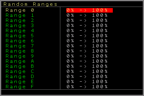
27
Scale screen
The Scale screen allows the setup of all scale behaviour (except for the table quantization, which is its own scaling system for other purposes).
Here you can edit the available scales, including fine-tuning, global and track behaviour, and the scaling behaviour for editing, input, and output.
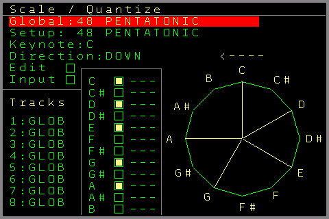
You can get to the scale screen through the Project screen
In general, there are 3 scale settings that define whether and which tracks are affected by the scaling. There is a global scale setting which applies to all tracks, and a per-track scale setting which overrides the global scaling. Per track you can define whether it should follow the global scaling (default), be excluded from scaling, or use its own dedicated scale.
There are 90 different scale presets available:
Chromatic, 6 Tone Symmetric, Altered, Augmented Hepatonic, Augmented, Balinese, Bebop, Bebop Locrian, Bebop Major, Bebop Minor, Composite Blues, Diminished, Dorian, Dorian B2, Double Harmonic Major, Egyptian, Enigmatic, Flamenco, Flat Sixth Pentatonic, Flat Third Pentatonic, Half-Whole Diminished, Harmonic Major, Harmonic Minor, Hirajosji, Hungarian Major, Hungarian Minor, Ichikosucho, In-Sen, Ionian Pentatonic, Iwato, Kafi Raga, Kumoijoshi, Lead Whole Tone, Locrian, Locrian 2nd, Locrian 6th, Locrian Major, Locrian Pentatonic, Lydian, Lydian 7th Pentatonic, Lydian 9th, Lydian Double-Harmonic, Lydian Diminished, Lydian Dominant Pentatonic, Lydian Dominant, Lydian Minor, Lydian Pentatonic, Major, Major Blues, Malkos Raga, Melodic Minor, Messiaens, Messiaens Mode4, Messiaens Mode5, Messiaens Mode6, Messiaens Mode7, Minor Hexatonic, Minor, Minor 11th Pentatonic, Minor Bebop, Minor Blues, Minor Pentatonic, Minor 6th Diminished, Minor 6th Pentatonic, Mixolydian, Mixolydian B6, Mixolydian Pentatonic, Mystery 1, Neopolitan Major, Neopolitan Pentatonic, Oriental, Pelog, Pentatonic, Persian, Phrygian, Phrygian Major, Piongio, Prometheus, Prometheus Neopolitan, Purvi Raga, Ritusen, Romanian Minor, Scriabin, Slocrian Pentatonic, Hepatonic, Todi Raga, Ultralocrian, Vietnamese, Whole Tone, and Whole Tone Pentatonic.
Additionally, the 4 scales (from scale 5A on) are ‘User Harmonics’, which are scales that can be dynamically created by pressing notes on a Midi keyboard. See the Input Assign setting in the Midi / I2C Setup Screen for more info.
You can create your own user scales as well.
At the top of the screen you can see the currently selected global scale. By default this is set to 00 Chromatic which includes all 12 notes within a western style octave. You can change the selected global scale using SHIFT+CURSOR LEFT/RIGHT/UP/DOWN.
The next row is the setup scale. This is the currently viewed scale and can differ from the selected global scale. If you changed one of the scale presets (indicated on the right side), you can revert the scale to the original by pressing SHIFT+DELETE.
Keynote → Defines the keynote of the scale. The scale will be transposed to the keynote relative to a plain C.
Direction → Changes the direction in which the next matching scale note is searched for. If set to UP, it looks for the next scale note higher than the current note (clockwise); DOWN searches anti-clockwise; and if set to COIN, a coin toss decides whether to search clockwise or anti-clockwise for the next match.
Edit → If enabled, all note input (e.g. in the pattern screen) only allows notes within the scale. If disabled, all notes of the chromatic scale can be entered as usual.
Input → This defines whether external input (like a Midi keyboard) should be scaled automatically on arrival. This is in addition to any output scaling and manipulates the incoming note stream directly. If disabled, the incoming stream is treated normally (although you might still hear scaled output if it is played directly).
Then there are the track settings, where you can set for each track whether it should be scaled by the global settings, bypass scaling, or use a dedicated scale for that track only.
Scrolling further is the note editing where you can individually change the selected scale. This can be changed by enabling/disabling notes within the scale (SHIFT+CURSOR UP/DOWN). Furthermore, you can change the fine-tuning per note (SHIFT+CURSOR LEFT/RIGHT).
The fine-tuned playback of notes works for Modular track notes, Audio Notes and I2C Notes but not for Midi.
You can see an indication of which notes are user-manipulated. SHIFT+DELETE in the 2nd Setup row will revert to the original scale.
On the right side you can see a chromatic circle diagram of the selected scale, with an indicator of the direction at the top.
The scales / user scales are saved and loaded with a project.
28
Mapping screen
This screen can be entered through the Project screen, the Midi / I2C Setup Screen or by pressing SHIFT+NERD twice from within most other screens.
The mapping screen is the main control center for manipulating any internal or external parameter with any other internal or external parameter. In the most basic usage, you would define a source, for example a CV input (or a Midi CC or I2C parameter or even the internal result of one of the envelopes….) and map it to a parameter like the row probability for track 3, or the speed of one automator LFO or the decay phase of internal envelope 7, just to name a few.
- Screen name
- Source function
- Source extra
- Source → destination
- Value of the selected row: hex, decimal, boolean
- Destination
- Destination function
- Mapping running
- Destination extra
- Row numbers
00–45 - A
CALCrow - Source
- Status: the field under the cursor
There are many sources and destinations to choose from — essentially all parameters you can think of. (There may still be something missing — feedback is always welcome!) Beyond simply mapping data, you can also manipulate all kinds of data, to the point that you can create a kind of algorithm / code. Think of value manipulation, calculations, start an action if any value reaches a defined level, scale parameters, manipulate sequences or playback caused by other events, generative stuff. For example, a bouncing ball or a Turing machine can be created with it and used to manipulate your sequences extensively.
The mapping screen has 6 columns and 70 rows, and each row can contain a source (3 columns) → destination (3 columns) definition. Each of the 70 rows is processed 1000 times per second (1kHz / each millisecond). The timing and how to use it are described further below. On the left of the rows there is a scrollbar together with a mini-map which shows which of the 70 rows are used.
The first 3 columns define the source, which is split into the base and 2 additional function parameters. Depending on the selected base, a related function can be chosen and, if needed, a 3rd type. For example, if you want to choose a Midi CC input as a source, it contains the Midi channel (Channel 5) and the controller number (Controller 14):
Or another example for a source would be the current setting of the row probability of track 3:
Some sources use only 2 parameters, some use 3. If a 3rd parameter is not available then the field is greyed out.
Columns 4–6 on the right side work the same way, but for destinations.
For example, to use the release value of envelope 3 as destination you would use the following:
As a full example of a row you could use CV Input 3 as a source and the MOD output 6 as a destination:
In this example, CV Input 3 is routed directly to the MOD6 output, updated up to 1000 times per second. Most values are updated ‘on change’. If the source value does not change, the destination will not be updated. There are some exceptions, which will be described with the relevant mapping destinations. Between the source and the destination you can see whether a mapping row is executed regularly by the mapping (‘>’) or excluded from the regular mapping ‘program’ flow (‘X’) (using the SKIP or XXMP/XLOD commands).
When the cursor is on a row, you can see the result of the source value on the top line of the screen (in hexadecimal and decimal: 0–FFF / 0–4095).
In this example you see the CV Input value changing when you change the input voltage.
Depending on the cursor position, the status line always shows the exact description of the command, or whether a parameter is missing for the source or the destination.
On the top right side you can see a ‘play’ symbol. You can pause the processing of the mapping by pressing the STOP button. This lets you edit the mappings without risk of any destination changing parameters while you browse. You can also enable ‘Stop on Edit: Yes’ in the Nerd Menu to automatically pause mapping execution when you edit any destination. Leaving the Mapping screen or pressing START will resume mapping execution. (Entering the Variable screen is an exception: the mapping stays paused there.)
With edit mode on, the OK button opens the Mapping Selector for the field the cursor is on.
OK takes the highlighted entry, SHIFT+OK leaves the field as it was.
The selector follows the way a row is built up. Choosing a base steps straight on to that base’s function list, and choosing a function steps on to its extra list, so a complete source or destination is entered in three presses. CURSOR LEFT walks back the other way, from the extra to the function and from the function to the base.
For the CALC and SKIP operands the selector shows a small editor for the two operands instead of a list — Constant, Threshold, Variable or Row for each side. These define the 2 values the calculation or function will work with. Additionally, there are some ‘chained’ functions which use 3 values/operands instead of 2. If the CALC command is in the source part, the previous row is used as the 3rd value. If the CALC command is in the destination part, the result of the source part is used as the 3rd value. A ‘chained’ example with CALC as source:
Row 00 reads the value of CV input 1 (the result is kept in row 00).
Row 01: the result is true (1) if the value of ROW 00 (the previous row) is between 2 and 7 (including 2 and 7), otherwise the result is false.
A ‘chained’ example with CALC as destination:
This produces the same true/false result, with the result of the source used instead of the previous row.
At any time, even with a paused mapping, you can execute just the current row (where the cursor is) by pressing SHIFT+OK. This can help with debugging, as you can execute lines one by one and check the results. The row will always be executed regardless of whether the source value has changed.
It is also possible to execute the rows from the sequencer patterns/tables/patches using the XMAP FX command, and the Drummatrix in the I2C/Multi patterns, which even allows manipulation of mapping rows. Here too, destinations are always executed regardless of whether the source changed.
There are also mapping sources and commands which let you skip the execution of multiple rows, so you can exclude parts of the mapping from regular execution and run them only from the patterns. These advanced features will be described with all the available sources and destinations. Skipped/excluded rows are indicated in the centre of the row, between the source and destination.
A source definition can be used in multiple rows to drive multiple destinations.
The result of a source, regardless of how it is generated, is always saved in the current row as a kind of variable. This is important to know, as this value can be used for further processing or calculations alongside the regular variables.
You can leave empty rows between function blocks for a better overview.
SHIFT+DELETE will clear the current field (and the additional parameter fields). SHIFT+UP+DELETE deletes the whole row and shifts the rows below upwards.
SHIFT+DOWN+DELETE INSERTS an empty row at the current position and shifts all rows below down.
Some parameters and functions refer to row numbers (and thus to their results). These row numbers will be automatically corrected when rows are shifted up or down, if necessary.
Mappings have a regular Mark / Copy / Paste, just like the sequencer and the pattern screen.
If you are in mark mode and press SHIFT+NERD to enter the Nerd Menu, then the export entry changes into ‘Export Part’ and only the marked rows (with all of their columns) are exported. The file gets a _PART added to its name, for example MYMAP_PART.MAP.
Such a partial mapping is imported into the position where the cursor is, so a block of mapping rows can be moved into any other mapping. If the imported rows would overwrite existing mapping rows, or if the block does not fit before the end of the mapping, a popup appears where START proceeds and STOP aborts the import. A partial import only writes those rows; the mapping variables and the mapping name of the project stay untouched. Row numbers that are used within the imported rows are not renumbered, so check these if the block is imported at a different position.
A complete mapping export and import replaces the complete mapping including the variables and the mapping name. (No need to mark anything in this case.)
It is good to know that there are 3 types of values that the sources can generate.
In most cases, values between 0 and FFF (4095) are generated, and the related functions scale to that range. For example, the CV input has a range of 0-FFF (4095) anyway, but a Midi CC value has only 128 values, so its range is 0 – 7F (127). This value is also scaled to 0 – FFF as the source result (you could calculate this back easily using one of the source functions if you really want to work with the 128 values).
FFF / 4095 is also the maximum value for mapping processing. As another example, an I2C input (using the SC.CV command, for example from a 16n) has a range from 0 – 3FFF (16383). In this case the value is scaled down to match the mapping range.
Another type of values that a source can generate are booleans. That means it can generate a 0 or a 1. An example is a gate input: if the gate is low (0 Volt) the result is 0, and if the gate is high (5 Volt) the result is 1. This could be used, for example, to turn a function on or off, or for further processing.
The last type is dedicated values. For example, if you use a Midi input with notes as a source, the result is the actual note number (0 – 127).
The same applies to destinations: some work with the full range, some with booleans or dedicated values.
The value types are explained for each source and destination.
As mentioned before, every row stores its result, which works as a kind of variable or storage. On top of that there are also 16 variables that can be used to store and exchange values on demand. Both the row values and the variables can be used to perform further calculations and processing. The 16 variables also have their own Variable Screen where you can see and manipulate the current values of all variables. You can get to the variable screen from the mapping screen by pressing the PATCH button. Note that a stopped mapping will stay stopped in the variable screen.
First, here is a list of all currently available source and destination types; a detailed explanation with examples follows below:
Mapping Sources (list)
| CV | CV Input1-4 | Value, Inverted Value, True/False by the threshold |
|---|---|---|
| CV Output 1-6 | ||
| MOD Output 1-6 | ||
| Trigger | Trigger/Gate Output 1-6 | No additional parameter |
| Trigger16 1-16, NSA 1-4 | ||
| Track 1-8 Matrix 1-16 | Fires the Trigger16 output or I2C drum-matrix cell that the track’s own drum matrix has that cell configured for (drum-matrix mute respected); no-op on other track types. | |
| Dualchord Trigger 1-2, NSA 1-4 | ||
| Audio 1-4 Gate (T7 Audio 1/2, T8 Audio 3/4) | ||
| Track | Track 1-8 | Probability 0 – Probability 8 where the probability destination depends on the track type |
| Pattern row (resolution based on ticks) | ||
| Run/Stop status | ||
| Note from Column 1 – 8 (returns the last played note from that column) | ||
| Sequencer row of the selected track. | ||
| Automator | Slot 0 – 7 | No additional parameter |
| Envelope | Envelopes 1-8 | Value (the envelope’s current output) |
| Gate (1 while the gate is on, else 0) | ||
| Current Stage (0 idle, 1 attack, 2 decay, 3 sustain, 4 release) | ||
| Setting values Attack, Attack Peak, Decay, Sustain, Release, Offset (scaled to 0 – FFF) | ||
| Midi | TRS Channel1-16 | Notes |
| Host Channel 1-16 | Any note = gate on, no note on = gate off | |
| Device Channel 1-16 | Velocity | |
| Learn | Channel Pressure/Aftertouch | |
| Pitchbend | ||
| Program Change | ||
| Gate from dedicated note | ||
| Velocity from dedicated note | ||
| Aftertouch from dedicated note | ||
| Midi CC | TRS Channel1-16 | Controller 0 – 127 |
| Host Channel 1-16 | Generate Pulse on a dedicated MCC number and value (event mode) | |
| Device Channel 1-16 | ||
| Learn | ||
| Midi NRPN(14 bit) | TRS Channel1-16 | Controller 0 – 9999 |
| Host Channel 1-16 | ||
| Device Channel 1-16 | ||
| Learn | ||
| I2C | SC.CV | Port 0 – 127 |
| Learn | ||
| Set/Get Variable | Variable A-P | Get Source |
| Row 00 – 45 | Constant 0 – FFF | |
| Calculate/Compute | Add | Two operands/parameters (Y and Z) with both: |
| Add with overflow | Constants 0-8 | |
| Subtract | Threshold | |
| Subtract with overflow | Variable A-P | |
| Multiply | Row 00 – 45 | |
| Multiply with overflow | Constants 9-167 | |
| Multiply * 0.1 | ||
| Multiply * 0.1 with overflow | ||
| Divide | ||
| Divide (2nd parameter * 0.1) | ||
| Divide (2nd parameter * 0.1) w. overflow | ||
| Modulo Y MOD Z | ||
| Bitwise AND | ||
| Bitwise OR | ||
| Bitwise XOR | ||
| Leftshift (without carry) | ||
| Rightshift (without carry) | ||
| Logical AND | ||
| Logical OR | ||
| Logical XOR | ||
| IF (Y < Z) | ||
| IF (Y<=Z) | ||
| IF (Y>Z) | ||
| IF (Y>=Z) | ||
| IF(Y=Z) | ||
| IF(Y<>Z) | ||
| Latching Flipflop | ||
| Invert with rising Y vs. Z | ||
| Invert with falling Y vs. Z | ||
| Track & Hold | ||
| Sample & Hold | ||
| Pass Z or 0 if Y | ||
| Count rising Y | ||
| Logical invert Y | ||
| Bitwise invert Y | ||
| Rightshift Y with overflow Z bits | ||
| Leftshift Y with overflow Z bits | ||
| Increment Y | ||
| Decrement Y | ||
| Minimum value of Y vs. Z | ||
| Maximum value of Y vs. Z | ||
| Average value of Y and Z | ||
| Pitch value Y to Note Number | ||
| Note Number Y to Pitch value | ||
| Random value between Y and Z (including) | ||
| Range former Row between Y and Z | ||
| Force passing value Y if Z is true | ||
| Generate onetime Pulse if Y > Z | ||
| Signed Modulo Y MODS Z | ||
| Load Indirect: value of row Y+Z | ||
| Increment and wrap between Y and Z | ||
| Bit test: is bit Z of Y set | ||
| Slew towards Y with a step of Z | ||
| Schmitt trigger Y vs. Z | ||
| Monoflop: Z ms pulse on a rising Y | ||
| True on one execution out of Z | ||
| Difference between Y and Z | ||
| Scale: quantize chained value into scale Y, keynote Z | ||
| Multiplex: Y if chained value is true, else Z | ||
| Clamp chained value inside Y and Z | ||
| Crossfade Y into Z by the chained value | ||
| Crossfade S-curve Y into Z by the chained value | ||
| Curve the chained value by Y, S-shaped if Z | ||
| Window: 1 while chained value is inside Y and Z | ||
| Fold chained value into the range Y – Z | ||
| Slew to the chained value, Y up, Z down | ||
| Accumulate chained signed step, held inside Y – Z | ||
| Clock divide: one pulse per Y edges, Z resets | ||
| Lookup: row Y + chained value, wrapped in Z rows | ||
| Shiftregister: chained bit on rising Y, Z bits wide | ||
| Normalise chained value from Y – Z back to 0 – FFF | ||
| Probability: pass Z with a chance of Y per chained edge | ||
| Skip amount of rows | Following for 1-16 (X) rows | Two operands/parameters (Y and Z) with both: |
| X rows if Y < Z | Constants 0-8 | |
| X rows if Y <= Z | Threshold | |
| X rows if Y > Z | Variable A-P | |
| X rows if Y >= Z | Row 00 – 45 | |
| X rows if Y = Z | Constants 9-167 | |
| X rows if Y <> Z | ||
| Global | Current mainclock row | No additional parameter |
| Sequencer Started / Stopped | ||
| Clock input state | ||
| Clock output state | ||
| Reset input state | ||
| Reset output state | ||
| Random value | ||
| BPM / Tempo | ||
| Insert from sequencer value | ||
| Generate Pulse through other row | ||
| Current Mainclock ticks | ||
| External Input | PC Keyboard (w Video Expander) | Numpad 0 -9, DOT |
| Sega Gamepad | A, B, C, X, Y, Z, Start, Mode, Up, Down, Left, Right | |
| Local Buttons | All NerdSEQ button states, including the Multi-IO Buttons X, Y and Z | |
| Multi-IO Encoder | Step size from Variable A-P or value of Row 00-45 | |
| PC Keyboard Encoder | Step size from Variable A-P or value of Row 00-45 | |
| Control | Execute following X Mapping rows | |
| Exclusive execute mapping rows | ||
| Execute mapping rows after project load | ||
| Execute following Mapping rows on rising edge of the previous row |
Mapping Sources (detailed)
Below you can find more detailed information about the mapping commands.
Sources (first 3 columns) (unless mentioned otherwise, the sources generate values between 0 and FFF (0 – 4095), so values are either 1:1, upscaled, or downscaled):
CV CV In/Output sources
IN1,IN2, IN3, IN4 → Are the 4 CV Inputs of the NerdSEQ.
CV1 .. CV6 → Are the real current CV output values.
MOD1 .. MOD6 → Are the real current MOD output values.
VAL → Passes the value as it is (0 – FFF).
!VAL → Passes the inverted value (FFF – value).
TH → Results in a 1 if the value is above the threshold (set in the Nerd Menu of the mapping) and in a 0 if it is not.
!TH → The same test but with an inverted result
TRIG Trigger/Gate Output Sources
TR1..TR6 → Is the real state of the Trigger outputs (Values 0 or 1)
1- 1..4-16 → Is the state of the outputs 1..16 of a Trigger16 expander. The first digit defines the selected expander NSA number 1-4 and the 2nd digit defines the output 1-16 on the selected expander, exactly like the Trigger16 destinations. This is best effort, since the T16 can’t report back its current state. Set/Reset and basic triggers are reported properly and can be reliably used.
D1-1..D4-2 → Is the state of the 2 trigger/gate outputs of a Dualchord expander. Same usage and best effort as the Trigger16 ones before.
AUD1..AUD4 → Is the gate of the 4 audio voices (Audio 1/2 on Track 7, Audio 3/4 on Track 8): 1 while a note is held.
TRCK Track-dependent sources
TRK1..8 → Is the track selection for the Track source.
PRB0..PRB7 → are the current probability percentages of the selected track. Which probability depends on which track type is being used (e.g. for a Modular track, PRB0 is the Note Probability).
PRB8 → is the current row probability percentage.
PTRW → is the current pattern row. It is based on the tick updates and therefore has a finer resolution (e.g. 6 ticks/step).
PRUN → Indicates whether a pattern on the track is running or not ( 0 / 1 )
NOT1..NOT8 → If a note was played in the selected column of this track, the last played note number will be used as source.
SROW → Returns the currently playing sequencer row of the track. Combined with the destination GLOB>SROW this can be used to let the sequencer screen scroll automatically with the sequence of the track.
AUTM Automator Results as source
SLT0…SLT7 → Selected automator slot. The bipolar automator result values get an additional offset so they fit the 0 – FFF range.
ENV Current Envelope results as a source
#1 .. #8 → Selected envelope
VAL → Passes the current envelope output (0 – FFF).
GATE → Results in a 1 while the gate of the envelope is on and in a 0 when it is off.
STAT → The stage the envelope is in: 0 idle, 1 attack, 2 decay, 3 sustain, 4 release.
ATK, ATKP, DECY, SUST, RELS, OFFS → The attack, attack peak, decay, sustain, release and offset settings of the envelope (0 – FE on the Envelope screen), scaled to 0 – FFF.
MIDI Midi ‘events’ as a source
TC1..TC16 → TRS-A/DIN Midi Input channels 1..16
HC1..HC16 → USB Host Midi Input channels 1..16 (needs Multi-IO Expander)
DC1..DC16 → USB Device Input channels 1..16 (needs Multi-IO Expander)
LRN → If set to this, the next received Midi note event will define (learn) the input device and the channel and if needed also the note number. The learn function also follows the extra 3rd column. You might want to set the 3rd column already to either Note or Gate or a specific note to learn also a note number or not. It doesn’t matter for which note you choose, the learn function will overwrite this to the learned note.)
NOTE → Generates a note number from a received note (0 – 127)
GATE → Counts all notes that are currently on and results in 0 if all notes are off.
VELO → Results in the velocity value of any played note (0 – 4095)
PRSR → Results in the channel pressure (channel aftertouch) of any played note (0 – 4095)
BEND → Results in the Pitch-Bend values of the channel (0-4095)
PGMC → Results in the Program Change values of the channel (0- 127)
C-0N to B-9N → If the selected note is on, the result is 1, otherwise 0. Use this if you want to turn on/off a function by a dedicated midi note
C-0V to B-9V → If the selected note plays, the velocity of this note is used as the result (0 – 4095)
C-0A to B-9A → Results in the polyphonic aftertouch for the selected note if available (0-4095)
MCC Midi Controllers (CC) as a source
TC1..TC16 → TRS-A/DIN Midi Input channels 1..16
HC1..HC16 → USB Host Midi Input channels 1..16 (needs Multi-IO Expander)
DC1..DC16 → USB Device Input channels 1..16 (needs Multi-IO Expander)
LRN → If set to this, the next received Midi CC event will define (learn) the input device and the channel. The learn follows the extra cell: if it is empty or holds a plain controller number then the channel and the controller are learned, and if it is already in the pulse/event mode then the controller number and the value of the received message are learned together, so an encoder click or a value button can be taught directly into the row.
# 0 to # 127 → is the controller number of the received CC.
In this mode the result would be the current value of the CC knob of the selected controller.
You can switch to pulse mode using SHIFT + CURSOR UP.
In Pulse mode the left ‘operand’ defines the Controller number and the right ‘operand’ defines the value of it:
0A01 → would use Midi CC controller 0A (#10) and Value 1.
If a Midi CC is received with the matching controller and value, a pulse is generated. This pulse can be used to increment / decrement values or to fire any other events. Some Midi CC endless encoders can be used with this.
NRPN Midi NRPN (Non-Registered Parameter Number) as a source
These are like Midi CC but can have more than 128 controller parameters and the values up to 14 bit. In all cases 7 or 14 bit NRPN messages will be auto-detected and will be scaled to 0-FFF (0 – 4095)
TC1..TC16 → TRS-A/DIN Midi Input channels 1..16
HC1..HC16 → USB Host Midi Input channels 1..16 (needs Multi-IO Expander)
DC1..DC16 → USB Device Input channels 1..16 (needs Multi-IO Expander)
LRN → If set to this, the next received NRPN event will define (learn) the input device and the channel.
# 0 – 9999 → is the NRPN parameter number / controller number
I2C I2C receptions as a source
Currently only the SC.CV command (0x10 or 0x11) is supported. The received 14 bit values are scaled to 12 bit (0 – FFF). Use this for example to directly receive your 16n faderbox or similar.
SCCV → Receive SC.CV or compatible (like ES.CO) commands.
LRN → Will learn the reception port with the next (or last) incoming I2C SC.CV Command.
#0 – 127 → is the selected port number for the reception
For a 16n and the first fader you would set it to I2C SCCV #0
VAR Sources and functions to use with the 16 Variables and the mapping rows
#A – #P → Selected Variable A to P
RW00 – RW45 → Selected mapping row 00 to 45
SRC → Will pass the value of the selected variable or row to the destination
#0 – FFF → Will set the selected variable or row to a fixed value. The result will also be passed to the destinations
CALC Calculations, Logical, Arithmetic and mapping control flow functions
These can be used to manipulate several values or to create a basic program flow / algorithm
The 3rd column parameters define the 2 operands (Y and Z) which are involved in the calculations or the processing. It is split into 2 parts where the left 2 digits define the first operand and the last two digits on the right define the second operand. This is indicated with a ‘|’ between the operands. The operands can be chosen from these sources: Constants (=0 to =8), which define the values 0 to 8, Threshold (TH) which uses the selected threshold value (define in the Nerd-Menu of the mapping), the 16 variables (VA to VP), the mapping row (00 to 45) and additional constants 9 to 167 (the additional constants are shown inverted so they are not mistaken for a mapping row). For example, if you want to involve row number 02 and variable A for any calculation you would choose 02VA in the 3rd column.
Furthermore: A Gate on means that the value goes from 0 to a value higher than 0 and stays there. A Gate off means that the value goes to 0 or is 0. A pulse/trigger means that the value goes from 0 to any value higher than 0 and then back to 0. Some CALC commands can use a 3rd parameter which would be derived from either the previous row (if the CALC is in the source part) or from the result of the source (if the CALC is in the destination part).
ADD → Adds the first Operand Y with the 2nd Operand Z with a maximum result of FFF. As an example if you want to add a 3 to Variable B:
For example, the result would be 5 if variable B currently holds the value 2. Note that the result is used as the source values to be passed to the destination. It doesn’t change the variable in any way.
ADD! → Adds the first Operand Y with the 2nd Operand Z with overflow. If the result is higher than FFF then it will overflow and start over from 0 (Result would be then the calculated result modulo FFF)
SUB → Subtract: Operand Y minus Operand Z. If the result is smaller than 0 then the result will be 0
SUB! → Subtract with overflow. Same as SUB but if the result is smaller than 0 it will overflow and continue at FFF. (Result would be then the calculated result modulo FFF)
MUL → Multiply Operand Y with Operand Z. No overflow.
MUL! → Multiply Operand Y with Operand Z with overflow.
MUL. → Multiply Operand Y with Operand Z and with 0.1 no overflow
MUL → Multiply Operand Y with Operand Z and with 0.1 with overflow
DIV → Divide: Operand Y / Operand Z no overflow (Division by zero is invalid but will result in 0)
DIV. → Divide: Operand Y / (Operand Z * 0.1). (Division by zero is invalid but will result in 0). No overflow
DIV → Divide: Operand Y / (Operand Z * 0.1). (Division by zero is invalid but will result in 0). With overflow
MOD → Modulo: Operand Y MOD Operand Z
BAND → Bitwise AND: Operand Y AND Operand Z
B OR → Bitwise OR: Operand Y OR Operand Z
BXOR → Bitwise XOR: Operand Y XOR Operand Z
LSFT → Leftshift: Leftshift Operand Y with Operand Z times. Without carry.
RSFT → Rightshift: Rightshift Operand Y with Operand Z times. Without carry.
LAND → Logical AND. Operands are true if they are > 0. AND is applied between those 2 operands, and the result is 0 or 1
L OR → Logical OR. Like LAND, result is 0 or 1
LXOR → Logical XOR. Like LAND, result is 0 or 1
IF < → IF expression: If Operand Y is smaller than Operand Z then the result is 1 else the result is 0
IF<= → IF expression: If Operand Y is smaller than or same as Operand Z then the result is 1 else the result is 0
IF > → IF expression: If Operand Y is greater than Operand Z then the result is 1 else the result is 0
IF>= → IF expression: If Operand Y is greater than or the same as Operand Z then the result is 1 else the result is 0
IF = → IF expression: If Operand Y is the same as Operand Z then the result is 1 else the result is 0
IF<> → IF expression: If Operand Y is greater or smaller than (not the same as) Operand Z, the result is 1, else the result is 0
LFLP → Logical FlipFlop with a set (Operand Y) and a reset input (Operand Z). If Operand Y is > 0, the FlipFlop is set (Result = 1) and if Operand Z is > 0 then the result is reset to 0. If both Y and Z are > 0, the result is 0
FLG^ → Result inversion on an incoming rising edge/pulse. The rising edge detection happens when Operand Y was smaller than Operand Z and becomes the same as or greater than Operand Z. A rising edge detection will invert a 1 to a 0 and the other way around.
FLGv → Result inversion on an incoming falling edge/pulse. The same as FLG^, but with a falling edge between Operand Y and Operand Z.
T&H → Track & Hold. Operand Y is the Gate and Operand Z is the value. As long as the Gate is high, the value from Operand Z is passed to the result. When the Gate is low, the result will keep/freeze the last gated Operand Z value.
S&H → Sample & Hold. Operand Y is the ‘trigger’ and Operand Z is the value. If Y was low and goes high, the value of Z is sampled once and passed as the result. The result is held until Y goes low again and goes high for the next sample.
PASS → Pass value or zero. This will pass the value of Operand Z if operand Y is > 0. If Operand Y is 0, the result is also 0.
CNT → Counter. Every trigger/pulse of Operand Y will be counted / added to the result. A trigger on Operand Z resets the result value.
DINV → Logical Invert. The result is 1 if Operand Y is 0 and the result is 0 if Operand Y is > 0.
INV → Bitwise Invert. The value of Operand Y will be bitwise inverted into the result.
SHTR → Right-Shift with carry. Operand Z is the number of bits used for the shifting and the carry (If for example the bits are set to 8 then every right shift will carry over to bit 7). The right shift shifts Operand Y each time this is called. An example for a series of 12 bit shifts would be: 0000 0000 0010 → 0000 0000 0001 → 1000 0000 0000 → 0100 0000 0000 and so on
SHTL → Left-Shift with carry. The same as right shift, but to the left. Bits shifted out of the selected number of bits will be carried to bit 0.
INC → Increment. Increments Operand Y (Result = Operand Y + 1). No Overflow.
DEC → Decrement. Decrements Operand Y (Result = Operand Y – 1). No Overflow.
MIN → Minimum function. The result is the lower/same value of Operand Y and Operand Z.
MAX → Maximum function. The result is the higher/same value of Operand Y and Operand Z.
AVRG → Average function. The result is the average value between Operand Y and Operand Z.
P2NT → Pitch to Note. Converts a pitch value (10 octave range 0 – FFF) into a note number (0 – 120). This can be used to feed CV NOTE destinations. This function is quantized so any value will snap to the nearest note (up or down).
NT2P → Note to Pitch. Converts a note number (0 – 120) to the 10 octave Pitch range (0 – FFF). This can be used to feed CV pitch destinations.
RNDM → Generates a random value between Operand Y and Z.
RNGE → Scale the chained value (see below) into a range between Operand Y and Z. NORM is its inverse.
FORC → Forces the value of Operand Y to the destination if Operand Z is > 0. The destination is forced to be executed regardless of whether the source value changed or not. Use this command with caution as it is possible that it executes 1000 times per second which might be too much for the selected destination (e.g. Midi or Expanders).
PULS → Generates a one-time pulse when a rising Operand Y becomes greater than Operand Z. Use this if you want to easily execute something only once on any ‘event’.
MODS → Signed Modulo: Operand Y MODS Operand Z
LDI → Load Indirect: the result is the value of the mapping row that Operand Y plus Operand Z points at (wrapped at row 45/69). This makes it possible to read a row that is selected while the mapping runs, so a block of rows can be used as an array, a wavetable or a step sequencer.
INCW → Increment and Wrap: counts the own result up by 1 on every execution and wraps inside the range Operand Y to Operand Z (both included). If Y is bigger than Z they are swapped, and a value outside the range restarts at the low end. Together with LDI this replaces a loop.
BIT → Bit test: the result is 1 if bit number Operand Z of Operand Y is set, else 0. Operand Z above 11 always results in 0.
SLEW → Slew: moves the own result towards Operand Y by at most Operand Z per execution. Operand Z = 0 jumps straight to Y. Use this to smooth a noisy CV input or to glide a value.
SCHM → Schmitt trigger: the result becomes 1 once Operand Y rises above Operand Z, and only returns to 0 once Operand Y falls 64 below Operand Z. The gap between the two points is what stops a noisy signal from chattering around the threshold.
MONO → Monoflop: on a rising Operand Y the result is 1 for Operand Z milliseconds and then 0 again, regardless of how long Y stays high. Operand Z = 0 counts as 1 millisecond.
EVRY → Create a pulse every x milliseconds. The result is 1 on one execution out of every Operand Z and 0 on the others. This is the easy way to slow a row down, for example in front of a Midi or expander destination that should not be executed 1000 times per second.
DIFF → Difference: the result is the distance between Operand Y and Operand Z, so it is never negative.
SCAL → Scale: the chained value is taken as a note number and quantised into the user scale defined by Operand Y, with Operand Z as the keynote (0 = C up to 11 = B).
MUX → Multiplex: the result is Operand Y when the chained value is not 0, and Operand Z when it is. A two-way selector.
CLMP → Clamp: the chained value, held inside the range of Operand Y and Operand Z. Either order works.
XFAD → Crossfade: Operand Y blended linearly into Operand Z by the chained value, where 0 is all Y and 4095 is all Z. A Z below Y simply fades the other way round.
XFDS → Crossfade S-Curve: the same fade as XFAD, but the blend follows an S curve instead of a straight line, so it eases in at the start and out at the end. The end points are the same as XFAD's and the result still stays between Operand Y and Operand Z.
CURV → Curve: the chained value bent by a response curve. Operand Y is the curve: 800 is linear, below 800 it is logarithmic (the value rises fast and then flattens) and above 800 it is exponential (it stays low and then climbs). Operand Z = 0 bends the whole range in one go; any other Operand Z mirrors the bend around the middle, which gives an S curve (Y above 800) or an inverted S (Y below 800).
WIN → Window: the result is 1 while the chained value sits inside the range of Operand Y and Operand Z, and 0 outside it.
FOLD → Fold: the chained value wrapped into the range of Operand Y and Operand Z. Where RNGE scales a value into a range, FOLD wraps it into one.
SLRF → Slew Rise/Fall: moves towards the chained value by at most Operand Y per execution upwards and Operand Z downwards. A rate of 0 jumps straight there, exactly as SLEW reads it.
ACCU → Accumulate: adds the chained value to its own result as a signed 12 bit step, where 0 to 2047 counts up and 2048 to 4095 counts down, and holds the total inside the range of Operand Y and Operand Z.
CDIV → Clock Divide: one pulse for every Operand Y rising edges of the chained value. A rising Operand Z restarts the division.
LUT → Lookup: the result of the row that Operand Y plus the chained value points at, wrapped inside a window of Operand Z rows. A window of 0 is the whole table of 70 rows.
SHFT → Shift Register: Operand Z bits wide. On a rising Operand Y it shifts its own result up by one and takes the chained value as the new lowest bit. Unlike SHTR and SHTL the data comes from outside, and between clocks the register simply holds.
NORM → Normalise: the chained value scaled from the range of Operand Y and Operand Z back up to 0 to 4095. A Y above Z turns the result around as well, so NORM undoes exactly what RNGE did.
PROB → Probability: passes Operand Z with a chance of Operand Y out of 4095. The roll happens once on each rising edge of the chained value and is then held for as long as it stays up, so a gate keeps its full length instead of chattering.
Good to know: MONO, EVRY and CDIV are usage limited. If more than 16 rows use MONO, EVRY or CDIV at the same time, the additional rows stay at 0.
SKIP A set of functions that allow skipping several mapping rows
This can be used to get a reduced execution pace of mapping rows, time related execution, conditional or ‘event’ related execution (for example if the CV Input 1 is higher than 5 Volt, then skip the following 5 rows, else the 5 rows will be executed).
The 3rd column again acts just as described in the CALC part of the mappings as a double source for 2 operands which are involved in the skipping decision.
The number of rows to be skipped is defined in the 2nd column. It is possible to skip up to 16 rows. The count starts from the next row. For example, if you have this command on row 02 with skip 2 rows, it would affect rows 03 and 04. Row 05 would not be affected and executed normally. If you need more rows, then add the same command with the same parameters and probably a different number of rows again after the last skipping block (in the example it would be in row 05). The result can be used as well: if the rows end up being skipped, the result is 1, else it is 0.
The live results of the skipped rows are visible in the middle of the mapping screen rows using the ‘>’ or ‘X’ indicator.
Listed for 1 to 16
as XX:
XX < → Skip XX rows if Operand Y is smaller than Operand Z
XX<= → Skip XX rows if Operand Y is smaller than or the same as Operand Z
XX > → Skip XX rows if Operand Y is bigger than Operand Z
XX>= → Skip XX rows if Operand Y is bigger than or the same as Operand Z
XX = → Skip XX rows if Operand Y is the same as Operand Z
XX<> → Skip XX rows if Operand Y is not the same as Operand Z
GLOB Global sources (uses only one parameter = 2nd column)
SQRW → Results in the current Mainclock row/step. The result is scaled to FFF
SRUN → Results in 1 if the sequencer is started and 0 if the sequencer is stopped.
CLKI → Results in the incoming Clock input state. (0 or 1)
CLKO → Results in the outgoing Clock output state (0 or 1)
RSTI → Results in the incoming Reset input state (0 or 1)
RSTO → Results in the outgoing Reset output state (0 or 1)
RAND → Generates a random value between 0 and FFF
BPM → Results in the currently selected or detected BPM
SEQV → Select this row as source of an I2C/Multi pattern. If one of the Multi-functional / I2C Track columns is selected as a Mapping source (set up in the Track Setup then the sequenced values (Numbers 0-120 for notes, 0-FFF for pitch values) are used as the result. Note that the row which is selected must match with the mapping row of the SEQV command.
PLSE → Generates a pulse from XMAP commands (e.g. from the sequencer). The result of the row is 1 for exactly one execution and 0 again on the next one. It fires when an XMAP, XXMP, XLOD or XSHT block executes this row (or when you press SHIFT+OK on it in the editor), and it also fires when another row writes a value into it with SETV RWxx: the result of the row is in that case the written value.
TICK → Results in the current mainclock ticks
RECM → Results in 1 while record mode is armed and 0 if it is not.
EXT External input sources
Currently external key/button presses are used (0 = button/key not pressed, 1 = button/key pressed)
KEYB → Is the PC Keyboard input of the Video Expander
NUM0..9 → Are the Number Keys / Number Block
DOT → Is the decimal dot in the Number Block
MUTE, PLAY, NEXT, PREV, STOP → Are the media keys of the keyboard. These might also have their own functions on the keyboard which can’t be controlled by the NerdSEQ.
Volume + / Volume – keys (if present) act as the PC keyboard's encoder. They are available as a mapping source through PENC below.
SEGA → Are the Sega Gamepad buttons: A, B, C, X, Y, Z, Start, Mode, Up, Down, Left, Right. Note that the Sega Gamepad function must be enabled in the Sega Gamepad Settings. Also take care of possible double functionality of a button if it is defined in both the mappings and the gamepad setup.
BUTN → Returns the status of the local NerdSEQ buttons:
CRUP → Cursor Up
CRDN → Cursor Down
CRLF → Cursor Left
CRRG → Cursor Right
STRT → Start
STOP → Stop
SHFT → Shift
OK → OK
UP → UP
DOWN → DOWN
SEQ → Sequencer/Mark
PTRN → Pattern/Copy
PTCH → Patch/Delete
TABL → Table/Record
AUTO → Automate/Nerd
PROJ → Project/Setup
MIOX → Multi-IO Button X
MIOY → Multi-IO Button Y
MIOZ → Multi-IO Button Z
You might want to disable the original MIO button behaviour in the Setup Screen and create your own functions using the mapping events.
MENC → Is the Edit knob/encoder of the Multi-IO Expander. Turning it steps the value of this mapping row up and down.
The Extra selects the step size by one of the 16 Variables or one of the 70 Mapping row results. The row value is kept between 0 and FFF and does not wrap around.
PENC → Is the encoder (or volume buttons) of a connected PC Keyboard with the same behaviour as MENC.
CTRL Main controlling functions
XMAP 0 – 69 Rows → Runs the following X rows once on every pass of the mapping. The rows are left out of the regular sweep; the XMAP row runs them, in direct order, each time the sweep reaches it, and once more whenever an external XMAP command calls it (e.g. from a pattern FX, a table or a patch). A SKIP in front of the XMAP row therefore switches the whole block on and off, however many rows it holds. The rows are always executed, whether their source changed or not. An XMAP row inside another block only runs when that block runs. This function is disabled if more than the available mapping rows are executed.
XXMP → Same as XMAP, except that the XXMP row never runs the selected rows itself: they are only executed when an external XMAP command calls them. The selected rows are kind of ‘encapsulated’, which you can also see by the indicator in the middle of the row. This would also be the preferred command to prevent rows from being executed by the mappings themselves.
XLOD → Same as XXMP. Additionally, the selected rows will be automatically executed once after the project loads. This can be used to apply any presets for some values or states in the NerdSEQ. Or for example to auto-start the sequencer after loading.
XSHT → Another variation of XXMP. It executes the following X rows once, triggered by the rising change (Logical 0 to 1) of the previous row's source. The one-shot must sit on row 01 or higher.
Mapping Destinations (list)
| CV | Pitch | Local CV 1-6 |
|---|---|---|
| Note | Local MOD 1-6 | |
| CV16 Expander 1-16, NSA 1-4 | ||
| Trigger/Gate | Gate | Local Trigger 1-6 |
| Trigger | Trigger16 1-16, NSA 1-4 | |
| Trigger value | ||
| Trigger force | ||
| Trigger value force | ||
| Track | Track 1-8 | Mute |
| Selected Track by cursor | Solo | |
| Select Track by Variable A-P | Pattern order | |
| Select Track by row 00-45 | Transpose | |
| Trigger delay | ||
| Probability 1-9 | ||
| CV glide | ||
| CV glide resolution | ||
| MOD glide | ||
| MOD glide resolution | ||
| Track Clock | ||
| Fire Patch | ||
| Pattern length | ||
| Pattern row | ||
| Pattern tick | ||
| Pattern shift up | ||
| Pattern shift down | ||
| Track Re-Sync | ||
| Track reset | ||
| FX1 Overrule | ||
| FX2 Overrule | ||
| FX3 Overrule | ||
| FX4 Overrule | ||
| Start/Cue sequencer track in selected row (0 – FE) | ||
| Start/Cue all sequencer tracks in selected row (0 – FE) | ||
| Jump selected track to another sequencer row (0-FE) | ||
| Jump all tracks to another sequencer row (0-FE) | ||
| Stop / Cue-stop selected track | ||
| Set euclidean position/basepoint | ||
| Local trigger set euclidean | ||
| Drummatrix 1-16 Set euclidean | ||
| Pattern cursor position | ||
| Pattern note at cursor | ||
| Pattern note at step 00 – 3F (00 – 64) | ||
| Pattern value at column step 00 – 3F (00 – 64) | ||
| Automator | Slot 0 – 7 | If LFO: |
| Slot defined by Variable A-P | Start | |
| Slot defined by result of Row 00-45 | Reset | |
| Speed | ||
| Offset | ||
| Invert | ||
| Clock | ||
| Amplitude | ||
| Waveform | ||
| Bitrate | ||
| Phase | ||
| Envelope | Envelope 1 – 8 | Attack |
| Envelope defined by Variable A-P | Attack Peak | |
| Envelope defined by result of Row 00-45 | Decay | |
| Sustain | ||
| Release | ||
| Offset | ||
| Gate | ||
| Fire | ||
| Toggle | ||
| Midi Controller | TRS Channel 1 – 16 | CC Controller number 0 – 127 |
| Host Channel 1 – 16 | NRPN (14 bit) Controller number 0 – 9999 | |
| Device Channel 1 – 16 | ||
| I2C | For I2C Multi-IO Port A+B | High byte = I2C address 0-127, low byte = port 0-127 |
| SC.CV (with slew) | ||
| SC.CV (no slew) | ||
| SC.CV (no slew not scaled) | ||
| SC.TR | ||
| ES.CO (disting EX / NT controller ID) | ||
| Audio | Audio parts 1 – 4 | Change Pitch |
| Change Note | ||
| Gate/Play Osc / Sample | ||
| Stop Oscillator / Sample | ||
| Select Sample/Osc | ||
| Offset | ||
| Backwards | ||
| Delay type | ||
| Delay time | ||
| Delay send | ||
| Delay feedback | ||
| FM Boost | ||
| Volume | ||
| Glide | ||
| Mute operator | ||
| Clone notes from | ||
| Clone coarse | ||
| Clone fine | ||
| Modulation source | ||
| Pulse Width Modulation | ||
| Wavefold | ||
| Bitcrush | ||
| Distortion | ||
| Sample Slot 0 – 11 | Sample Loop start position | |
| Sample Loop end position | ||
| Sample Loop combined start+end position | ||
| Set Variable | Variable A – P | From source |
| Row 00 – 45 | Reset if source = true | |
| INC^ Increment on a rising source | ||
| INCv Increment on a falling source | ||
| DEC^ Decrement on a rising source | ||
| DECv Decrement on a falling source | ||
| Random Ranges | Random Range 0 – 15 | Minimum % |
| Maximum % | ||
| Global | Transpose | |
| Swing | ||
| Tempo / BPM | ||
| Masterclock steps | ||
| Scale | ||
| Scale keynote | ||
| Resync tracks | ||
| Reset player | ||
| Row as Midi record source | ||
| Buttons | Sequencer/Mark | |
| Pattern/Copy | ||
| Patch/Delete | ||
| Table/Record | ||
| Automate/Nerd | ||
| Project/Setup | ||
| Start | ||
| Stop | ||
| Shift | ||
| OK | ||
| Down | ||
| Up | ||
| Cursor Up | ||
| Cursor Down | ||
| Cursor Left | ||
| Cursor Right | ||
| Screens | Sequencer | |
| Pattern | ||
| Patch | ||
| Table | ||
| Current Values | ||
| Automator | ||
| Envelope | ||
| Track Setup | ||
| Random FX | ||
| Mapping | ||
| Variable | ||
| Scaling | ||
| Nerd Menu | ||
| Project | ||
| Setup | ||
| Sample Select | ||
| Record Setup | ||
| Midi/I2C Setup | ||
| Screen Saver | ||
| Track Assign | ||
| Load Project | ||
| Save Project | ||
| Mode | Edit Mode | |
| Record Mode | ||
| CV Input Live Mode | ||
| Pattern Scroll Mode | ||
| Set number of Edit Steps | ||
| Set to Multi-IO Button Mode X (general purpose knob) | ||
| Set to Multi-IO Button Mode Y (note entry) | ||
| Set to Multi-IO Button Mode Z (euclidean triggers) | ||
| Set Sequencer Row | – | |
| Set Scale Direction | ||
| Scope Input 1 | ||
| Scope Input 2 | ||
| Scope Input 3 | ||
| Scope Input 4 | ||
| Scope Trigger Input | ||
| Fill pattern commands/settings | Fill current playing Pattern 1..8 / all now | |
| Magic Fill current playing Pattern 1..8 / all now | ||
| Notes, Trig/Sample, MOD toggles | ||
| Note range Min/Max | ||
| Note Density Min/Max | ||
| With Note Off switch | ||
| Combine Note+Trig switch | ||
| Trigger type Min/Max | ||
| Drummatrix Mask 1-8 9-16 | ||
| Trigger Density Min/Max | ||
| Sample/Wave range Min/Max | ||
| Mod/Note/Pitch Range Min/Max | ||
| Mod density Min/Max | ||
| Sample Volume Range Min/Max | ||
| Midi Velocity Range Min/Max | ||
| Scale | ||
| Keynote for scale | ||
| Interval Mode | ||
| Interval Parameter | ||
| Range direction | ||
| Behaviour | ||
| Offset | ||
| Allowed Columns | ||
| Remove % | ||
| New Pattern Length for Fill | ||
| CV16 | Envelope Settings 1-8: | CV 1-16, NSA 1-4 |
| Glide Speed | ||
| Glide Resolution | ||
| Attack | ||
| Amplitude | ||
| Release | ||
| Fire Oneshot | ||
| Fire A/R | ||
| LFO Settings 1-8: | ||
| Type | ||
| Speed | ||
| Amplitude | ||
| Start | ||
| Reset | ||
| Stop LFO/Envelope | ||
| Table | Table 00 – 1F | Speed |
| Running Table on Track 1-8 | Type | |
| Running Table on selected Track | Quantize | |
| Chord | ||
| Range Low | ||
| Range High | ||
| Preset | ||
| Add Tick | ||
| Start Table on Track 1-8 | ||
| Stop Table | ||
| Midi | TRS Channel 1 – 16 | Note On |
| Host Channel 1 – 16 | Note Off | |
| Device Channel 1 – 16 | Note On, Note Off | |
| Pitchbend | ||
| Program Change | ||
| Advanced Note On and Off on gate | ||
| Advanced Note On and Off on trigger | ||
| Dualchord | NSA1,2,3,4 | Note 1-8 |
| Pitch 1-8 | ||
| Wave On/Off 1-8 | ||
| LFO 1-8 Speed | ||
| LFO 1-8 Amplitude | ||
| LFO 1-8 Offset | ||
| LFO 1-8 Phase | ||
| Stereo Deepness | ||
| Wave 1-8 PWM | ||
| Wave 1+2+3+4 PWM | ||
| Wave 5+6+7+8 PWM | ||
| Wave 1-8 Detune | ||
| Wave 1+2+3+4 Detune | ||
| Wave 5+6+7+8 Detune | ||
| Output 1-2 Spread | ||
| Waveform 1-8 Triangle, Sine, Saw, Pulse amount | ||
| Waveform 1+2+3+4 Triangle, Sine, Saw, Pulse amount | ||
| Waveform 5+6+7+8 Triangle, Sine, Saw, Pulse amount | ||
| Wave 1-8 Morph | ||
| Wave 1+2+3+4 Morph | ||
| Wave 5+6+7+8 Morph | ||
| Wave 1-8 Glide | ||
| Wave 1+2+3+4 Glide | ||
| Wave 5+6+7+8 Glide | ||
| Wave 1-8 Velocity | ||
| Wave 1+2+3+4 Velocity | ||
| Wave 5+6+7+8 Velocity | ||
| Set Preset | ||
| Voice Envelope Attack | ||
| Voice Envelope Decay | ||
| Voice Envelope Sustain | ||
| Voice Envelope Release | ||
| Filter Cutoff | ||
| Filter Resonance | ||
| Filter Envelope Amount | ||
| Noise Volume | ||
| Filter Mode | ||
| Fold Drive | ||
| Fold Bias | ||
| Skip number of rows | Following for 1-16 (X) rows | Two operands/parameters (Y and Z) with both: |
| X rows if Y < Z | Constants 0-8 | |
| X rows if Y <= Z | Threshold | |
| X rows if Y > Z | Variable A-P | |
| X rows if Y >= Z | Row 00 – 45 | |
| X rows if Y = Z | Constants 9-167 | |
| X rows if Y <> Z | ||
| Video | Start/cue/stop shaders | Shaders 1-8 |
| Selected or by value | ||
| Shader commands | Position X/Y, Time Amplify, Alpha | |
| Shader Modulators | Modulators 1-16 | |
| Shader Envelope | Shader envelopes 1-8 Gate, Fire, Attack, Sustain, Release, Offset | |
| Shader LFO | Shader LFOs 1-8 Start/Stop, Wave, Speed, Amplitude, Offset, Phase | |
| Controls | Exclusive Execute Rows on rising edge | Number of rows 1-69 |
| Exclusive Execute Rows on falling edge | ||
| Exclusive Execute Rows on changing edge | ||
| Calculate/Compute | All CALC functions, exactly as listed for the CALC source | Two operands/parameters (Y and Z), exactly as the CALC source. ‘Chained’ CALC types use the Source as the 3rd parameter |
Mapping Destinations (detailed)
The destinations in a mapping row use the columns 4, 5 and 6. In the same way as with the sources, the 4th column is the basis while the others are function parameters.
Nearly all destinations are only executed if the source value changes, with some exceptions. These exceptions are mentioned in their function descriptions.
CV General CV Output (Local and CV16 Expander) destinations for Notes or Pitches
The defined CV outputs will be set to the notes/pitches.
PTCH → Sets the pitch defined by the source value 0-FFF.
NOTE → Sets the pitch defined by the note value. (Accepts numbers from 0 – 120)
CV 1..6 → Are the local CV outputs
MOD 1..6 → Are the local MOD outputs
1 – 1 → Is the destination for the CV16 expander. The first digit defines the selected expander NSA number 1-4 and the 2nd digit defines the output 1-16 on the selected expander.
TRIG General Trigger / Gate Destinations for the local Trigger/Gate outputs and the Trigger16 Expander
GATE → Sets/resets the Gate of the selected output.
TRIG → Fires a Trigger (Selected Default Trigger Type in Setup Screen), if the source changes from 0 to something > 0.
TVAL → Sends the Trigger with the selected value (e.g. value FD for trigger toggle, see the trigger types in
the Pattern Screen of the Modular Track).
Note that the value will be fired every time the source changes.
TRG* → Fires a Trigger (Selected Default Trigger Type in Setup Screen) with every execution of the row. You might want to limit this execution with the SKIP functions and fire the trigger only when you want to.
VAL* → Fires the Trigger defined by the value every time the row is executed. Limit the execution as described with the TRG* function.
TRCK Track / Pattern related destinations
TRK1..8 → Selected Track for the function
SLCT → Select the track by cursor, e.g. in the sequencer screen via the track columns or within a pattern or the last selected track.
VA..VP → Select the track dynamically by a variable
RW00..RW45 → Select the track dynamically by a row result
MUTE → Mute track if the value is > 0. Unmute if the value is 0.
SOLO → Solo the track if the value is > 0. Unsolo if the value is 0.
PORD → Select Pattern order. The pattern order will be changed immediately. The selection of the 18 different pattern order types is handled with the Values 0 – FFF (0 = Normal order, FFF = Drunk order).
TPS → Transpose Track. The center (no transposition) is 7FF. Transposing is 5 octaves down (Values 0 – 7FF) and 5 octaves up (values 800 – FFF).
TDLY → Changes the Trigger delay setting of the track (if available). Values 0 – FFF change it from 0 – 16.9ms.
PRB1..PRB8 → Changes the probability percentage of the track. The selected probability is defined by the track type. For a modular track that is 1 = Note probability, 2 = Trigger probability, 3 = MOD probability, 4 = Table probability, 5,6,7,8 = FX 1..4 probability. The selected probability is shown in the status line. Values 0 – FFF for the probability values from 0 – 100%.
PRB9 → Row Probability.
GL C → Glide Speed for the Track CV output (if available)
GLCR → Glide Resolution for the Track CV output (if available)
GL M → Glide Speed for the Track MOD output (if available)
GLMR → Glide Resolution for the Track MOD output (if available)
TCLK → Track clock settings. 800 is the middle point with the regular track clock. Higher values are the multipliers and lower values are the dividers. The setting is changed immediately.
PTCH → Fire a selected patch. The patch number is selected with the previous row. The patch fires if the current row changes from 0 to 1 (logic change).
LGTH → Changes the Pattern Length. This affects either the currently playing pattern or the currently selected pattern if you are in the pattern screen of the track.
PROW → Manipulates the row position of the currently playing pattern of the track.
TICK → Generates a tick for the selected pattern. This function only works if the track clock is turned off, so it accepts the clock from this function here. The ticks are generated if the value before was 0, and the new value is the number of ticks that should be added. For example, if a track has the regular groove settings of 6 for each step, then you would iterate between 0 and 6 to move a step forward in the track. The iteration could simply be generated by a CV input with a trigger connected. Manipulate the result of this input with the CALC+PASS function where Operand Y uses the row of the CV Input and Operand Z uses a constant of 6. The destination of the last row would be TICK of the selected track.
SHUP → Pattern Shift UP. Shifts up the currently playing pattern of the track on every 0 to value toggle of the source. The value also defines the number of shift steps.
SHDN → Pattern Shift DOWN. The same as SHUP, but down.
SYNC → Initiates a track re-sync, which happens once the Mainclock runs through the zero-cross.
RSET → Track Reset. A pulse for this function will reset the track to its start position.
FX1..FX4 → Activates the override for the FX values 1..4. Any filled- in FX in the defined FX column will always be overridden by the mapping result value.
STRT → Start/Cue Sequencer Track. The values 0-FE define the row in the sequencer screen. Behaves like the Start button.
STRW → Start/Cue Sequencer Row. The values 0-FE define the row in the sequencer screen. Behaves like SHIFT+Start.
JMPT → Jump to Sequencer Row. Jumps directly to another pattern in the selected sequencer row of the selected track (0 – FE) and keeps playing until the pattern is finished.
JMPR → Jump to Sequencer Row. Jumps all running tracks directly to another pattern in the selected sequencer row (0 – FE) and keeps playing until the pattern is finished.
STOP → Stops the selected Track (Cue stop). Behaves like the Stop button.
ECLP → Sets the euclidean start/base-position for the following euclidean commands.
ECLD → Sets the euclidean values of the local trigger column for the currently playing or currently selected pattern (if in the pattern screen). The values 0 – FFF define the euclidean fill from 0 to the pattern length.
EC1 to EC16 → Sets the euclidean values of the drummatrix columns if available (Trigger16/I2C/Multi Patterns/Tracks)
CRSR → Manipulates the cursor row in the pattern. This could be used to fill in values while externally ‘navigating’ around with the row.
CRNT → Inserts a note and a trigger (Selected Default Trigger Type in Setup Screen) at the current cursor position in the pattern. A value of 0 will remove the note and the triggerpoint.
NT00 to NT3F → Inserts a note and a triggerpoint into the selected or the playing pattern at the selected step/row. (00 – 3F / 0 – 63). A value of 0 will remove the note and the triggerpoint. As an example, this could be used to insert a complete pattern on the fly using up to 64 faders or knobs or any other source.
CU00 to CU63 → Inserts a value at the current cursor position and the selected row.
PNC1 to PNC8 → Inserts the note from the mapping row above into note column 1 – 8 of the row the track is playing right now. It fires when this row’s value rises from 0, the note is scaled like NT00 to NT3F and a note value of 0 removes the note. Columns the track type does not have are ignored (CV/Gate 1, MIDI 1 – 4, CV16 and I2C 1 – 6, Dualchord 1 – 8). The note is only written, it is heard the next time the playhead reaches that row.
AUTM Destination to manipulate automator functions and settings
SLT0..7 → Selected automator slot.
VA..VP → Select automator slot by variable
RW00..RW45 → Select automator slot by row result
Of the Automator types, currently only the LFO automators can be manipulated from the mappings!
STRT → A value > 0 starts the Automator LFO
RST → Any change of the value will reset the LFO
SPED → Change the LFO Speed value
OFFS → Change the LFO Offset Value
INV → If the value is > 0, the LFO wave is inverted
CLCK → Select the clock source of the LFO
AMP → Set the amplitude (00 – F7) of the LFO
WAVE → Change the LFO waveform.
BIT → Change the bitrate/resolution of the LFO
PHAS → Change the start phase of the waveform
ENV Destination to change the local envelope settings and to fire the envelopes
#1 to #8 → Selected envelope
VA..VP → Select envelope slot by variable
RW00..RW45 → Select envelope slot by row result
ATK → Attack
ATKP → Attack Peak
DECY → Decay
SUST → Sustain
RELS → Release
OFFS → Offset
GATE → Sets the Gate to start the envelope. Value > 0 = Gate on, Value 0 = Gate off
FIRE → Fire/start the envelope (one shot)
TOGL → Toggles the envelope gate when receiving a pulse
MCON Send Midi controller (CC) or 14-bit NRPN controller messages
TC1..TC16 → TRS-A/DIN Midi Output channels 1..16
HC1..HC16 → USB Host Midi Output channels 1..16 (needs Multi-IO Expander)
DC1..DC16 → USB Device Output channels 1..16 (needs Multi-IO Expander)
#0 to #127 → defines the Midi controller (CC) numbers to which the values are sent.
N 0 to 9999 → defines the controller numbers for the 14 bit NRPN message. The 12 bit value is upscaled to 14 bit.
I2C Send various I2C commands to the selected I2C Port and Address on the Multi-IO Expander
A CV → SC.CV command with slew
ACVS → SC.CV command without slew
ACVX → SC.CV command, without slew, not scaled (exact value)
A TR → SC.TR command
AESC → ES.CO command, sets the disting EX/NT controller ID
Same commands available for Multi-IO I2C Connector B (e.g. B CV, B TR or BESC)
Address / Port → each 0-127, shown together as one 4 digit hex value: the I2C Address (default 0x31, or 0x41 for AESC/BESC) and the Port for the destination.
AUDI Destination to change all kinds of audio-related parameters
#1 to #4 → Defines the selected audio part. #1 and #2 are the first 2 waves/samples which usually output on the left audio output (sample 7); #3 and #4 are used for the audio parts for the right audio output (sample 8). The audio part can be a sample or a waveform.
PTCH → Changes the pitch of the selected audio part for 10 octaves (0 – FFF).
NOTE → Changes the note (via note number 0 – 120) of the selected sample/waveform
GATE → Sets the gate of the selected audio part (0/1). For example, the envelopes can be triggered by the gate, if connected. The sample/waveform will start using the (last) selected pitch/note, sample/waveform and volume.
ONOF → Turns the selected audio part off (1) and resets its gate.
WAVE → Select either the sample or the waveform for the selected audio part (0 – 11 = Sample slots, 12 = Sine, 13 = Triangle, 14 = Ramp, 15 = Sawtooth, 16 = Pulse, 17 = Noise)
OFFS → Changes the offset of the selected sample (0 – FFF scaled to the sample length) or changes the pulse width of the pulse wave (800 = 50/50).
BACK → Switches from forward (0) to backward (1) playback of the sample.
DLYT → Sets the delay type of the Audio part 1&2 or 3&4. Types 0: SHORT HQ, 1: LOFI, 2: MORE LOFI, 3: FAST
DYTI → Sets the delay time of the Audio part 1&2 or 3&4.
DLYS → Changes the delay send parameter for 1&2 or 3&4
FDBK → Changes the feedback parameter for 1&2 or 3&4
BOST → Changes the FM Boost parameter (all audio) 0-4
VOLM → Changes the volume of the selected audio part
GLID → Changes the glide of the selected audio part
MUTE → Mutes the selected audio part (0 / 1)
CLON → Select the audio part to clone notes from (0 = OFF, 1-4 = parts)
CORS → Select the coarse difference for the note cloning (0-119 = negative coarse, 120 = same coarse, 121–240 = positive coarse)
CFIN → Finetune of the coarse (0-119 = negative finetune, 120 = same tune, 121–240 = positive finetune)
MSRC → Selected audio modulation source. 0 = none, 1 = OP1, 2 = OP2, 3 = OP3, 4 = OP4, 5 = OP1+2, 6 = OP2+3, 7 = OP3+4, 8 = OP1+3, 9 = OP2+4, 10 = OP1+4, 11 = OP1+2+3, 12 = OP2+3+4,
13 = OP1+3+4, 14 = OP1+2+4, 15 = OP1+2+3+4
PWM → Pulse width modulation setting for the pulse waveform
WFLD → Wavefold settings for the selected audio part
BCSH → Bitcrush setting for the selected audio part
DIST → Distortion setting for the selected audio part
SP0 to SP11 STAR → Sets the loop start position of the selected sample slot
END → Sets the loop end position of the selected sample slot
POS → Changes the loop start and end position of the selected sample slot (moves the loop window)
SETV Variable functions for the 16 variables
V A to V P → Selected variables A to P
RW00 to RW45 → Selected mapping row 00 to 45
SRC → The result of the source value will be stored into the selected variable/row. This is also one option to manipulate rows from outside the mapping execution.
RST → The selected variable or row will be reset if the source result is > 0.
INC^ → The selected variable or row is increased by 1 on every rising source value. It stops at FFF.
INCv → The same, but on every falling source value.
DEC^ → The selected variable or row is decreased by 1 on every rising source value. It stops at 0.
DECv → The same, but on every falling source value.
RNDM Change the minimum and maximum values of the random ranges
RG0 to RG15 → Selected range 0 to 15
LOW → Change the minimum % value of the selected range
HIGH → Change the maximum % value of the selected range
Invalid values will automatically be corrected (e.g. min >= max).
GLOB Global destinations to manipulate different parameters
TPS → Global transpose settings. 0-7FF = negative transpose, 800 = no transpose, 801 – FFF = positive transpose.
SWNG → Swing setting. 0-7FF = Negative swing, 800 = No swing, 801-FFF = positive swing.
TMPO → Change the tempo/BPM: 0 – FFF = 1 – 500 BPM
MCLK → Change the number of mainclock steps: 0 – FFF = 1-64 steps
SCAL → Select global scale 0-FFF = Scale 0 – 90
SLKN → Selected scale keynote 0-FFF = Keynote C to B
SYNC → Resync all tracks command if true
RSET → Reset player (reset playback rows to 0) if true
MREC → Use row as Midi Record source (Mapping must be set up in the Midi / I2C Setup Screen and this mapping row must be selected in the defined track ( Track Setup Screen). It is used as a record source to record into the MOD column of a modular track.
BUTN → Buttons of the sequencer. If the result is > 0, the button is pressed. If the result is 0, the button is not pressed. This allows for external control of the NerdSEQ buttons.
SEQ → Sequencer/Mark button
PATN → Pattern/Copy Button
PTCH → Patch/Delete Button
TABL → Table/Record Button
AUTM → Automate/Nerd Button
PROJ → Project/Setup Button
STRT → Start Button
STOP → Stop Button
SHFT → Shift Button
OK → OK Button
DOWN → ‘Page’ down Button
UP → ‘Page’ up Button
C UP → Cursor up Button
CDWN → Cursor down Button
CLFT → Cursor left Button
CRGT → Cursor right Button
SCRN → Changes to the selected screen if the result is > 0 (if possible)
SEQ → Sequencer Screen
PATN → Pattern Screen
PTCH → Patch Screen
TABL → Table Screen
CVAL → Current Values Screen
AUTM → Automator Screen
ENV → Envelope Screen
TSET → Track Setup Screen
RDFX → Random FX Screen
MAPP → Mapping Screen
VAR → Variable Screen
SCAL → Scaling Screen
NERD → Nerd Menu
PROJ → Project Screen
SETP → Setup Screen
SMPL → Sample Select Screen
RSET → Record Setup Screen
MI2C → Midi/I2C Setup Screen
SSVR → Screen Saver Screen
TASS → Track Assign Screen
LOAD → Load Project Screen
SAVE → Save Project Screen
MODE
EDIT → Enable/Disable Edit mode
RECORD → Enable/Disable Record mode
LIVE → Enable/Disable Live Mode for the CV Input
SCRL → Enable/Disable Pattern View Scroll Mode
EDTS → Set Edit Steps
MIOG → Set to Multi-IO Button Mode X (general purpose knob)
MION → Set to Multi-IO Button Mode Y (note entry)
MIOT → Set to Multi-IO Button Mode Z (euclidean triggers)
SROW → Current Sequencer Row
SDIR → Set current Scale Direction (UP/DOWN/COIN)
SCP1..4 → Scope inputs 1 to 4
SCTV → Scope Trigger input
FILL → Fill Pattern manipulations.
FI 1..8 → Fill playing Pattern on track 1..8 (on a rising edge)
FI * → Fill all playing patterns on all tracks (on a rising edge)
FIM1..8 → Magic Fill playing Pattern on track 1..8 (on a rising edge)
FIM* → Magic Fill all playing patterns on all tracks (on a rising edge)
TNOT → LOW: Notes will not be filled, HIGH: Notes will be filled
TTRG → LOW: Triggers will not be filled, HIGH: Triggers will be filled (also for sample slots)
TMOD → LOW: MOD will not be filled, 1: Notes will be filled in MOD, 2: Pitches will be filled in MOD (also for Sample Volume and Midi Velocity)
NTLO, NTHI → Note range, min/max
NDLO, NDHI → Note density, min/max
NOFF → 1 = with note off, 0 = without note off
CNT → 1 = combine Note + Trigger, 0 = do not combine
TTLO, TTHI → Trigger type min/max
DML → Drummatrix mask 1-8
DMH → Drummatrix mask 9-16
TDLO, TDHI → Trigger density min/max
SRLO, SRHI → Sample/Wave slot min/max
MPLO, MPHI → MOD, Note, Pitch range min/max
MDLO, MDHI → Mod density min/max
VOLO, VOHI → Sample/Wave volume range min/max
VCLO, VCHI → Midi velocity range min/max
SCAL → Selected scale
KEY → Keynote for scale
IVAL → Set Interval mode
IVPR → Interval parameter
RDIR → Range direction
BHVR → Behaviour
OFFS → Offset
COLS → Allowed columns
REM% → Percentage of filled-in values to remove
PLEN → New pattern length
CV16 Settings, manipulation and execution of CV16-related functionality
1-1 to 4-16 → The 6th column (3rd destination column) is used to define the CV16 destination NSA1..4 CV, Output 1..16
GLCV → Glide Speed
GLCR → Glide Resolution
Settings and execution for all 8 Envelopes
EVxA → Envelope x Attack setting
EVxS → Envelope x Sustain/Amp setting
EVxR → Envelope x Release setting
EVxO → Execute Envelope in Oneshot Mode (> 0 = execute)
EVxX → Set Gate (start) Envelope X on > 0, reset Gate on 0
If envelopes have been started, they take over the CV output function just as if they were started from the sequence.
LFxT → LFO x Type (0 – 7: Sine, Triangle, Sawtooth, Ramp, Square, Noise, Random and Trigger)
LFxS → LFO x Speed
LFxA → LFO x Amplitude
LFxX → LFO x Start
LFxR → LFO x Reset (the reset function also applies to the envelopes)
STOP → Stop Envelope or LFO Modulator and give control back to the sequence (e.g. notes)
TABL Settings for the tables
TB00 to TB1F → Directly selected table
TRK1 .. TRK8 → Currently running table on Track 1..8
TSEL → Currently running table on selected track (cursor in sequencer screen, in pattern or last used track)
SPED → Table speed
TYPE → Table execution type (e.g. loop, one shot etc.)
QUTZ → Quantize settings (None, Down, Up, Coin)
CHRD → Select/change Chord for table
RGLO → Random Range low
RGHI → Random Range high
PRST → Select and fill in table preset
TICK → Add 1 Table Tick on a rising edge (or via XMAP)
STT1..8 → Start Table on Track 1..8
STOP → Stop Table (only if a track is selected)
MIDI Send to Midi
TC1..TC16 → TRS-A/DIN Midi Output channels 1..16
HC1..HC16 → USB Host Midi Output channels 1..16 (needs Multi-IO Expander)
DC1..DC16 → USB Device Output channels 1..16 (needs Multi-IO Expander)
NTON → Note On with Velocity 127. Uses Note numbers 0 – 127. Please be aware that this only sends a Note On and can cause ‘hanging’ notes if not used properly.
NTOF → Note Off. Uses Note numbers 0 – 127.
NOTE → Sends a Note On (Velocity = 127) followed by a Note Off.
PBND → Sends PitchBend Data. 800 hex is the middle point.
PGMC → Sends a Program Change command (0-127)
NTGT → Sends a Midi Note On if the source goes from 0 to a value and a note off if the source goes from a value to zero. The note number is derived from the previous row (0-127). A note off always uses the last used Note On number. This destination will not be executed if it is placed on row 0.
NTTR → Sends a Midi Note On and Off if the source goes from 0 to a value (trigger). The note number is derived from the previous row (0-127). This destination will not be executed if it is placed on row 0.
DUAL Dualchord Expander commands
NSA1,2,3,4 → Defines the selected Dualchord NSA Channel
NOT1..8 → Changes (and starts) the selected wave 1..8 with the selected note 0-127
PTC1..8 → Changes (and starts) the selected wave 1..8 with the selected pitch 0-4095 / 0-FFF
OOF1..8 → Turns the selected wave off (0) or on (any other value)
L1..8SP → Sets the Speed of Dualchord LFO 1..8 (0-FFF). 0-C0 (192) change to a synchronized LFO (128,64,32,16,8,4,2,1 steps and 2x,3x,4x,5x,6x per step) and values higher than C0 (192) set the speed of a free running LFO from the slowest to the fastest.
L1..8AM → Sets the amplitude of the Dualchord LFO 1..8 (0-100% scaled to 0..FFF)
L1..8OF → Sets the offset of the Dualchord LFO 1..8 (-50% to +50% scaled to 0-FFF, default midpoint at 800)
L1..8PH → Sets the phase of the Dualchord LFO 1..8 (0 – 360 degrees scaled to 0..FFF)
STEO → Sets the stereo depth (0-100% scaled to 0-FFF)
W1..8PW → Sets the pulse width of the pulse wave 1..8 (Ratio from 100-0 to 0-100 scaled to 0-FFF, default midpoint 50-50 at 800)
WAPW → Sets the pulse width of the 4 pulse waves 1,2,3,4 (Ratio from 100-0 to 0-100 scaled to 0-FFF, default midpoint 50-50 at 800)
WBPW → Sets the pulse width of the 4 pulse waves 5,6,7,8 (Ratio from 100-0 to 0-100 scaled to 0-FFF, default midpoint 50-50 at 800)
W1..8DT → Sets the detune of the Waves 1..8 (-128 to +127 scaled to 0-FFF, default midpoint (no detune) at 800)
WADT → Sets the detune of the 4 Waves 1,2,3,4 (-128 to +127 scaled to 0-FFF, default midpoint (no detune) at 800)
WBDT → Sets the detune of the 4 Waves 5,6,7,8 (-128 to +127 scaled to 0-FFF, default midpoint (no detune) at 800)
ASPR → Sets the detune spread (detune between each waveform) of the 4 Waves 1,2,3,4 (0-255 scaled to 0-FFF, no detune at 0) BSPR → Sets the detune spread (detune between each waveform) of the 4 Waves 5,6,7,8 (0-255 scaled to 0-FFF, no detune at 0)
W1..8TR → Sets the triangle wave velocity of the Waves 1..8 (0-100% scaled to 0-FFF)
W1..8SI → Sets the sine wave velocity of the Waves 1..8 (0-100% scaled to 0-FFF)
W1..8SA → Sets the sawtooth wave velocity of the Waves 1..8 (0-100% scaled to 0-FFF)
W1..8PU → Sets the pulse wave velocity of the Waves 1..8 (0-100% scaled to 0-FFF)
WATR → Sets the triangle wave velocity of the 4 Waves 1,2,3,4 (0-100% scaled to 0-FFF)
WASI → Sets the sine wave velocity of the 4 Waves 1,2,3,4 (0-100% scaled to 0-FFF)
WASA → Sets the sawtooth wave velocity of the 4 Waves 1,2,3,4 (0-100% scaled to 0-FFF)
WAPU → Sets the pulse wave velocity of the 4 Waves 1,2,3,4 (0-100% scaled to 0-FFF)
WBTR → Sets the triangle wave velocity of the 4 Waves 5,6,7,8 (0-100% scaled to 0-FFF)
WBSI → Sets the sine wave velocity of the 4 Waves 5,6,7,8 (0-100% scaled to 0-FFF)
WBSA → Sets the sawtooth wave velocity of the 4 Waves 5,6,7,8 (0-100% scaled to 0-FFF)
WBPU → Sets the pulse wave velocity of the 4 Waves 5,6,7,8 (0-100% scaled to 0-FFF)
W1..8MO → Sets the morph value of the waves 1..8 (scaled to 0-FFF)
WAMO → Sets the morph value of the 4 waves 1,2,3,4 (scaled to 0-FFF)
WBMO → Sets the morph value of the 4 waves 5,6,7,8 (scaled to 0-FFF)
W1..8GL → Sets the glide amount of the waves 1..8 (scaled to 0-FFF)
WAGL → Sets the glide amount of the 4 waves 1,2,3,4 (scaled to 0-FFF)
WBGL → Sets the glide amount of the 4 waves 5,6,7,8 (scaled to 0-FFF)
W1..8VL → Sets the velocity of the waves 1..8 (0-100% scaled to 0-FFF)
WAVL → Sets the velocity of the 4 waves 1,2,3,4 (0-100% scaled to 0-FFF)
WBVL → Sets the velocity of the 4 waves 5,6,7,8 (0-100% scaled to 0-FFF)
PSET → Set preset 1-4
The following destinations belong to the voice block of the Dualchord:
EATK, EDCY, ESUS, EREL → Attack, Decay, Sustain and Release of the voice envelope
FCUT → Sets the filter cutoff
FRES → Sets the filter resonance
FENV → Sets the filter envelope amount (800 is the middle point / no modulation)
NOIS → Sets the noise volume
FMOD → Selects the filter mode (Off and 19 modes from 0-FFF)
FDRV → Sets the fold drive
FBIA → Sets the fold bias (800 is centered)
SKIP Same functionality as the SKIP functions of the mapping sources
VISU Visual functions in combination with the Video Expander
SHSL → Visual Shader Select
NOSH → Stop shader now. Stops a currently running shader immediately.
SH1..8 → Start shader now
SHSL → Start shader that is selected by the source now CNOS → Cue stop shader. Stops a running shader on the zero cross of the mainloop.
CSH1..8 → Cue shader. Starts the shader on a zero crossing.
SHCU → Cue shader selected by the source value
SHAD → Shader manipulation functions
POSX → Sets the X position of the shader (u_mouse.x) if supported
POSY → Sets the Y position of the shader (u_mouse.y) if supported
TAMP → Sets the shader time amplification
ALPH → Sets the shader alpha (u_alpha) if supported
MODS → Shader Modulators
MD1..16 → Sets the modulation values (u_modulator1..16) of the shader (if supported)
SENV → Shader Envelope Settings
E1..8GT → Shader Envelope 1..8 Gate
E1..8FI → Fire shader envelope 1..8
E1..8AT → Shader Envelope 1..8 Attack
E1..8SU → Shader Envelope 1..8 Sustain
E1..8RE → Shader Envelope 1..8 Release
E1..8OF → Shader Envelope 1..8 Offset
SLFO → Shader LFO Settings
L1ST → Shader LFO 1 Start
L1WV → Shader LFO 1 Waveform
L1SP → Shader LFO 1 Speed
L1AM → Shader LFO 1 Amplitude
L1OF → Shader LFO 1 Offset
L1PH → Shader LFO 1 Phase
CTRL One shot exclusive execute rows
XSH^ → Rows 1..69. Execute the next X rows on a rising edge
XSHv → Rows 1..69. Execute the next X rows on a falling edge
XSH! → Rows 1..69. Execute the next X rows on a changing edge (logic 0/1← >1/0)
CALC The same calculation functions and behaviour as the CALC source
The result becomes the result of this row, which can be used by other rows as a parameter/value. With the ‘chained’ CALC operations the 3rd parameter is not taken from the previous row, but instead directly from the source value.
A CALC destination is always executed, even when the source value has not changed.
29
Variable screen
The variable screen stores 16 user-defined variables, which are mainly used for the mappings.
You can get to the variable screen from within the Mapping Screen by pressing the PATCH button. (Return to the mapping screen with the PATCH button as well.)
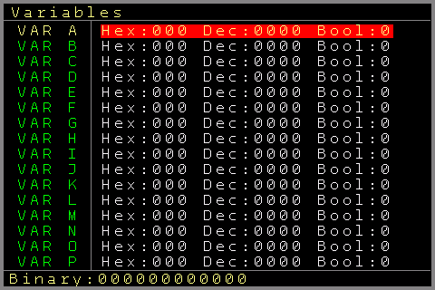
On the variable screen you can see 16 rows which are for the 16 variables A to P. Next to the names you see the current HEX, decimal and Boolean values of the variables. If the cursor is on a variable, you can also see the binary value of the selected variable. The displayed values are updated at an interval of 100ms, so if a variable changes quickly, you might not see all steps in between.
The variables can be changed using SHIFT+LEFT/RIGHT/CURSOR UP/DOWN, or they can be reset to zero by using SHIFT+DELETE.
If you paused the mapping screen before, the mapping execution also stays paused in the variable screen.
30
User Interface screen
This screen is dedicated to changing the user interface colours and font. There are 6 different fonts available ranging from Solid to Geek.
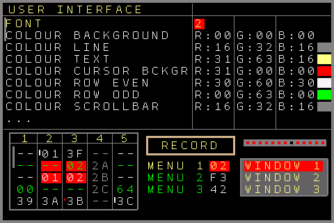
As for the colours, you can change the following User Interface colours:
- Background, Lines, Text, Cursor Background, Even Rows, Odd Rows, Scrollbar, Play Cursor, Record frame, Muted Text, Windows Fill, Windows Lines, Clock Bars.
All colours can be edited in their Red, Green and Blue components. On the right side you can view the selected colour values as well as examples of how the colours would look on the screen.
Uppercase Font → When enabled, all text is entered and shown in uppercase.
Choose Import or Export to import or export User Interface presets/skins onto/from the SD Card.
On the lower side of the screen, examples of all screen components are visible.
Use the Save option to save the font and colour settings so they are recalled after a power cycle.
The Reset Colour option resets the colours to the original colour scheme.
31
Reorganize screen
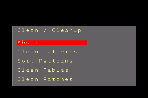
This screen gives you some options to clean up and sort unused patterns, tables or patches.
- Abort → Brings you back to the Project screen
- Clean Patterns → Clears and releases unused Patterns
- Sort Patterns → Enters the Pattern Sort screen which lets you reorder and defragment your patterns. It shows a scrollable list of all pattern slots — each with its number, per-track "in use" squares, type, and name — and on the left there is also a minimap marking which slots are filled. Press OK to grab the pattern under the cursor, move it to a new position, and press OK again to drop it. Use ‘Pack’ to automatically pull all used patterns to the top and push empty slots to the bottom. All changes are just a preview until you select ‘Apply’, which renumbers the patterns and updates every reference to them in your song. ‘Abort’ leaves everything unchanged. Note that applying stops playback and clears the single-pattern undo.
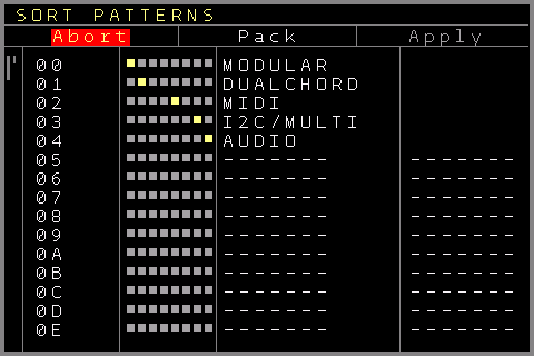
Pattern Sort screen - Clean Tables → Clears and releases unused and empty Tables. A release of unused but not empty tables must be done with the special Nerd Screen / Menu Function in the Table Screen.
- Clean Patches → Clears and releases unused Patches. Note that the clean functions stop the playback first.
32
Sega Gamepad settings
This screen can be entered from the Setup Screen. It is used to test and set up a connected Sega Gamepad (or compatible clones). Pad movements and button presses are visualised here.
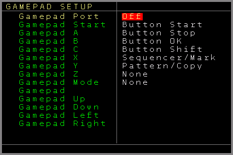
Navigate to a button and use SHIFT+LEFT/RIGHT to assign the gamepad buttons to several functions:
Gamepad Port On or Off. Off completely disables the Gamepad functionality if you have no Gamepad or it is not connected. This frees some resources. Please note that if you updated from a version earlier than V2.0, the port will be disabled once!
A (6 button) Sega Gamepad provides the following buttons: Start, A, B, C, X, Y, Z and Mode. Gamepads with additional buttons (like shoulder buttons) are available, but only the mentioned buttons are compatible with Sega systems.
These buttons can be assigned to the following functions:
Buttons of the NerdSEQ: Sequencer/Mark, Pattern/Copy, Patch/Delete, Table/Record, Automate/Nerd, Project/Setup, Start, Stop, Up, Shift, OK, Down
Additional mappings:
Gate1..6 → Sets the local gates 1..6 when the button is pressed and releases them when the button is released.
Trigger 1..6 → Fires a trigger on a button press
Trigger and Gate settings can also be recorded if the function is enabled in the record settings.
Sample 1..4 → Plays the selected sample (last played sample, last selected pitch). Samples 1 and 2 are played from audio output 7, and 3 and 4 from audio output 8.
Mute Track → Mutes the selected track (or drum part with Trigger16)
Solo Track → Solos the selected track (or drum part with Trigger16)
Jump Track → Jumps to the newly selected pattern in a track at the same position where the sequencer was (same as the OK button if edit is disabled).
Jump Row → Jumps to the new patterns of the complete row
None → Nothing selected for the gamepad. Use this if you don’t need any function for this button.
It is also possible to use the gamepad button as a Mapping Source in the Mapping Screen. This allows you to connect a large set of functions to the Gamepad buttons, in addition to the ones described here. In that case, you would most likely set the button to None here.
The D-Pad can only be used for general navigation and can’t be assigned to any other function in this screen. The settings are saved automatically when leaving the menu.
33
Midi expanders
You can add one of the Midi Expanders to your NerdSEQ to gain advanced Midi functionality. Think of clock input and output, playing and recording from Midi (Midi→CV conversion), Midi CC and NRPN control of all NerdSEQ parameters, polyphonic multi-channel Midi recording and sequencing, parameter, program change or drum sequencing and much more.
All Midi Expanders have the same Midi functionality, except for the Multi-IO, which has 2 additional Midi ports, each of which can be used independently. The Midi (and I2C) features can be used all over the NerdSEQ; refer to the different parts of the manual for the dedicated functionality (e.g. Patterns, Automators, Midi Input Setup, Mapping …).
Normally you can only connect and use one Midi Expander with one NerdSEQ. The exception is the Multi-IO, which can also be used together with the regular Midi-IO Expander. When used together, the Midi ports of the Midi-IO Expander are disabled, but the Sega Gamepad port can still be used. There is also a dedicated Sega-Gamepad Port Expander available.
Midi-IO Expander
It enhances the NerdSEQ with a Midi In and a Midi Out (DIN5) port and a connector for a Sega Gamepad controller. A Sega Gamepad (Sega Genesis 6 Button Controller), which can be used for navigation, editing, live playing and further manipulations, can be connected to the Gamepad connector.17
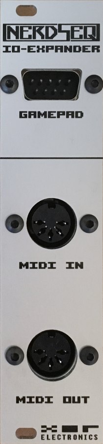
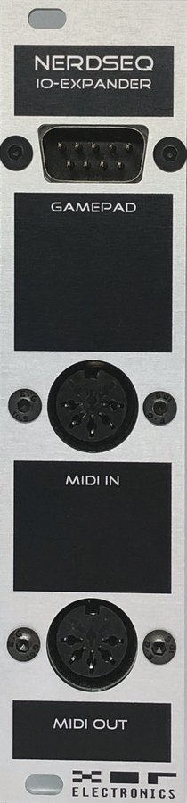
IO-Expander Installation
Connect the 12Pin ribbon cable header to the PAD-Midi port on the backside of the NerdSEQ. The expander is powered from the NerdSEQ. The NerdSEQ doesn’t scan the Midi-Interface, so it just works when connected.
2HP TRS-A Midi-Expander
Smaller version of the Midi Expander without the Sega Gamepad port. It has 1 TRS-A input, 1 TRS-A output and a TRS-A Thru port which can be used as an output as well. TRS-A is used since it is the Midi standard. All other aspects of the standard are also respected (e.g. electrical specifications, opto-isolation etc.).
Specifications
- 2HP width
- Midi In/Out with the standardized Midi TRS-A minijack connections.
- Additional port for Midi Thru/Out
- 3 Adapter cables to connect with regular 5 Pin DIN Midi
2HP TRS-A Midi-Expander Installation
Connect the 12Pin ribbon cable header to the PAD-Midi port on the backside of the NerdSEQ. The expander is powered from the NerdSEQ. Use the TRS-A to DIN Midi cables which are included with the Expander if you need to connect to classic 5 pin DIN Midi ports. Use an optional TRS-A to TRS-B Midi Adapter if you need to connect to gear which uses TRS-B Midi connections.
The NerdSEQ doesn’t scan the Midi-Interface, so it just works when connected.
You need to use stereo audio cables for the connection between different Midi gear. Mono patch cables don’t work with TRS Midi!
Multi-IO Midi & I2C Expander
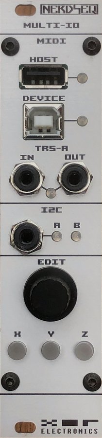
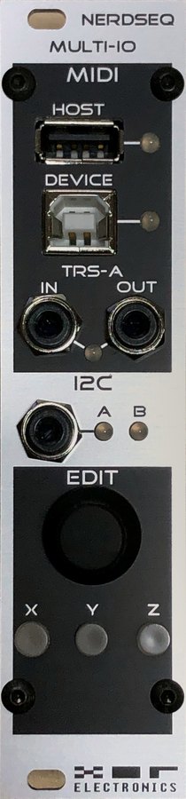
The Multi-IO is the latest Midi Expander for the NerdSEQ, which contains 3 independent Midi Ports (TRS-A Midi in and out, USB Host Midi and USB Device Midi) and 2 freely configurable I2C Ports (Leader/Follower), both located as standard 3-pin headers on the backside, with one additionally on the front panel as a TRS jack (for example to connect an external 16n directly on the front). Furthermore, there is an encoder which can be used to ‘dial-in’ parameters/values or notes. Finally, there are 3 buttons for selecting new modes for data input together with the Edit encoder.
The TRS-A Midi can be used as a regular Midi Port (adapter cables for regular DIN Midi are included; TRS-A to TRS-B adapters are optional). The USB Host port can be used to directly connect a Launchpad or a Midi Master Keyboard. It also supports hubs, so both and more can be connected at the same time using a USB hub. The port is specified for a current of up to 500mA (at 5 Volt), but that also depends on your rack's capabilities.
The USB Device port can be directly connected to any modern computer and will appear as a class compliant USB Midi input and output port on it.
Specifications
- 3 independent Midi Ports on the Front: TRS-A, USB Host and USB Device Midi Port
- 2 I2C Ports, both on the backside and one additionally on the front with a TRS Jack
- I2C with selectable Pullup (none, 3.3V, 5V)
- Encoder to ‘dial-in’ notes and values
- 3 buttons to change input modes
- 6HP, 40mm deep
- Power: ~20mA (+12V) 0mA (-12V) 0mA (5V)
- Standard USB Host power up to 500mA at 5 Volt (limited by rack power, equals ~200mA on the +12V rail)
Multi-IO and I2C Additional Installation guide
The Multi-IO basically needs 2 connections: one to the Eurorack bus board for power and another one to the NerdSEQ for communication.
Connect the 10 pin connector to the Rack power bus. Connect the 12 pin cable from the Midi-Bus Port (the outside port) to the Midi-Pad port of the NerdSEQ. If needed, connect the middle ‘Thru’ port to another Midi-IO Expander or to the Gamepad Expander. The ‘Thru’ port is only for the Gamepad functionality, so it won’t give more Midi functionality with the other Midi Expanders.
The I2C pullup jumpers should be in the 3.3 Volt position if no I2C gear is connected. Otherwise, please follow further I2C instructions of your connected gear and the tutorial in the NerdSEQ manual. If the other gear already has its own pullup resistors, you can leave the jumpers open (remove the jumper or only connect one leg of it so you don’t lose it). So far all I2C gear should be fine using 3.3 Volt pullup resistors. Never hot-plug the I2C ports; only connect I2C gear when both the expander and the gear are powered off. If you connect any of the I2C ports, be sure to connect your gear 1:1 = GND to GND, SCL to SCL and SDA to SDA. Usually only one pullup is needed in the I2C chain, so check whether your gear already has internal or enabled pullups and that the voltages match.
You can chain multiple I2C devices together in parallel, with the basic rule that only one leader is allowed per chain.
I take no responsibility for any damage to your gear or the Multi-IO caused by using I2C in your setup.
If you are new to I2C, it is recommended to check out ‘A users guide to I2C’.18
Within the NerdSEQ, you can choose for either port whether it should be a leader or a follower (Midi / I2C Setup Screen).
Translated to Midi, a ‘leader’ would typically be the Midi Out port and a follower would be the Midi In Port. So you usually connect one ‘Leader’ to one or multiple ‘Followers’.
The leader sends or requests the data and the follower responds to that request. With the NerdSEQ port, you can always see on the front LED whether the communication works. In detail: if the port is a leader port, you will see the indication of the communication only if the Follower also responds properly. If there is no response, for example caused by a wrong connection or a wrong address or malfunction/collision, the LED will not show anything. However, you can always be sure the NerdSEQ tried to initiate the communication with the ports and addresses you specified. No LED = no proper communication.
The same applies the other way around: if you use a ‘follower’ port, you will only see an indication if a valid packet has been received on the correct address.
Some configuration examples:
NerdSEQ I2C (Leader) → ER301 (Follower, Address 0x31)
→ distingEX/NT (Follower, Address 0x41)
→ Just Friends (Follower, Address 0x70)
These can all be connected together on one leader port if the addresses are different for every follower. For example, multiple ER301s can also be connected if they use different addresses. Look up in the gear's manual how to change their receive addresses if you want to use multiple units.
NerdSEQ I2C (Follower, Address 0x31) ← 16n ‘Clones’ (Leader Mode)
All 16n clones (like Sweet 16, Atov 16n, Michigan Synth Works F8R Fader Banks etc.) should work together with the NerdSEQ if they are configured well and use one of the latest firmwares. Things to consider when using the official 16n firmwares:
If the NerdSEQ is the follower, you need to set the 16n to leader mode. The NerdSEQ port needs to be set to address 0x31. The 16n will scan the I2C port 10 seconds after power-on, and if it doesn’t find any I2C device, it will deactivate the I2C communication. That means that most of the time you would need to power cycle the 16n once if you have freshly set up the NerdSEQ I2C port to be used as a 16n follower. The settings will be saved into the Multi-IO, so once it is set up it will work (also if you start a fresh project with the NerdSEQ, the default OFF configuration with Address 0x31 also reacts to the 16n requests) if you power on everything together for example. If your 16n is an external device with external power, turn your rack on first and then the 16n. You don’t have to wait until the NerdSEQ has finished its startup. Also be aware that the I2C setup can change with every project. So you might make a dedicated ‘template’ project file which already has your I2C and Midi configuration matching your hardware setup.
I currently ‘forked’ the 16n sourcecode and will provide an alternative version which allows using multiple 16n fader banks on one I2C port and which won’t do the I2C scan after 10 seconds, but assumes that the Multi-IO is always connected. That will help with the power-on behaviour.
Also, as mentioned, multiple 16n can be connected. The easy way is one 16n on each I2C port, so you can have 32 faders working directly.
But you could also connect up to 4x 16n faderboxes on one I2C port of the NerdSEQ. All the 16n then have to be set to follower mode, though, and all need different addresses (either by compiling an alternative firmware using addresses 0x34, 0x35, 0x36 and 0x37) or using the upcoming pre-compiled firmwares which I will put up on github. The NerdSEQ can be set up like this already. The alternative firmwares for the 16n will follow. In this configuration, the NerdSEQ polls each 16n fader independently and takes over the new fader position on change.
Once the 16n is configured and working (LED indicator when you move the faders) you can use it as a source for all kinds of functionality in the Mapping Screen
Note that even though it shows a 1 on the first fader, a 2 on the 2nd etc., the real port which is sent from the 16n starts with 0. So for fader 1 you would set up I2C → SCCV → #0.
NerdSEQ I2C (Follower) ← Teletype (Leader Mode)
There is no Teletype integration at the moment, but this is/was planned after the upcoming Teletype firmware release (V5.0). However, it can already be used with the Teletype in a minimal way. The Teletype SC.CV commands can already be used to change parameters in the NerdSEQ. The NerdSEQ port would then be set to be a follower, Address 0x31 (or 32, 33) and as a 16n input.
Other configurations, for example a 16n (follower) and an ER301 (follower) together on one I2C port, are also possible but not recommended. That’s because using a 16n in follower mode generates much traffic on the I2C port and even though this works, it means less available bandwidth and possibly slight latencies with the ER301 sequencing. It is like using multiple Midi Gear on only one Midi Port. So best practice is to have the gear that has to be sequenced on one I2C port and the fader boxes etc. on the other port.
Multi-IO Functionality
Unlike the ‘classic’ Midi-IO and TRS-A Midi expanders, the Multi-IO provides 3 Midi Ports. This means that all 3 ports can receive and send independent Midi data. For example, you could decide which of the ports should send out the Midi Clock data (like clock out on the TRS-A and the Host port but not on the device port). The Midi receive part can be flexibly configured for each Midi Port and its dedicated channels for a large range of functionality, starting with Midi Note play, record, change parameters, launch patterns and much more. The USB Host port allows you to directly connect different Launchpad devices, which can then be used with the → Launchpad Integration. All modern (class compliant) Launchpad (LP Mini, MK2, MK3, Pro, X) devices are reported to work with it. The Host port also allows the use of a USB hub (most hubs should work) so you can connect for example a Launchpad and use a Midi Master Keyboard on another channel at the same time. (Always keep your Eurorack power in mind; you might need to use a powered USB hub. The Multi-IO allows a 500mA current on the USB 5 Volt of its port (~200mA on the +12 Volt rail of the Eurorack power).)
So far all tested USB Host gear works, but please let me know if something doesn’t work for you. Please keep in mind that only class compliant gear is supported, so old Midi gear which needs special drivers might not work.
The USB Device port is a standard class compliant Midi Device for your computer. If you connect it to your computer it will add a new Midi input and output port (XOR NerdSEQ) on your computer which you can use with your DAW or any other Midi capable software. Since it is class compliant, it works with all modern operating systems without the need of any drivers. The Multi-IO uses a very fast microcontroller so all device port traffic is so-called ‘realtime’. This might not apply to your computer setup, operating system, DAW etc. So any latency or jitter on the USB Device port is always generated by the computer and there are many things that can influence this like the CPU, the type of USB Ports in the computer (internal hub, shared resources etc.), Audio Latency, Operating System, software you use and so on.
The TRS-A Midi Ports are standard Midi ports following the Midi standard for TRS and the electrical specification (opto-isolation etc.). There is a TRS input and an output jack which can be converted to a classic 5 Pin DIN Midi connector using the adapter cables which are delivered together with the Multi-IO. Since the Midi standard (TRS-A)19 is used, all gear that uses TRS-B needs a special A to B adapter cable which you can get easily from your preferred music instrument shop or from the XOR webshop.
You need to use stereo audio cables for the TRS connection between different Midi gear. Mono patch cables don’t work with TRS Midi!
There is an LED indicator for each of the Midi ports which shows outgoing (green) and incoming (red) Midi data.
Next to the Midi Ports there is an I2C port located on the front. It uses a common TRS connector for the I2C. The TRS configuration is TIP = SDA, RING = SCL and Shield = GND.
As far as I know, there are no TRS-A / TRS-B issues here.
This is the same port as Port A on the backside. So you could use the Front jack together with the backside connection if your I2C configuration allows it. Also the pullup configuration is the one for Port A. The I2C connectivity has been described before. To connect any gear with it you need a stereo cable. Normal Eurorack patch cables won’t work!
I can’t remind you enough: Never hotplug the I2C connectors. Don’t feed it with control voltages or anything like that.
The Edit knob and the 3 function buttons X, Y, Z
The edit knob is an endless encoder (no detent = no click) which can be used for multiple purposes. The use case depends on which button mode is selected.
If button mode X is active, it works as a general purpose input knob. You can go onto every parameter and change its value in the same way as you would do it with the cursor keys. Regular turning of the knob increments/decrements the value (wherever the cursor is) in fine steps. Holding the X button and turning the knob will result in larger increments / decrements.
Button Mode Y works within a pattern; if active, turning the knob will insert a music note together with a trigger-point (on Modular tracks; see the note below for the other track types). You can use the cursor to go to another step or maybe use the launchpad and directly select the step on the grid. It is another fast way to create/dial in a sequence directly into the selected steps. If you hold the Y button and turn the knob, it will remove the Note and the Trigger point again at the selected position.
Button Mode Z also works within a pattern and it allows you to insert trigger positions in the euclidean way. Turning the knob to the left decreases the euclidean positions and turning it to the right increases the euclidean positions. Please note that the euclidean start point will be at the selected cursor row. So you might want to go to position 1 for the euclidean input (or not).
Holding the Z button allows the trigger column to shift up/down. A combination of button modes Y and Z allows you to insert interesting sequences quickly.
Please note that the knob and button XYZ functionality is still being extended. Button Mode Y works on every track type except Video: on MIDI, Audio, Dualchord and CV16 tracks turning the knob changes the note under the cursor (holding Y removes it), and on Trigger16 and I2C tracks it adds or removes euclidean hits in the drum-matrix column you last selected (holding Y shifts that column). Button Mode Z works on Modular, Audio and Dualchord tracks and, again on the last selected drum-matrix column, on Trigger16 and I2C tracks. More functionality and flexibility will be added.
Each of the three buttons and the encoder can have its built-in function switched off individually, under Setup Screen → Encoder & Multi-IO Buttons. A button whose function is off still lights its LED when pressed but no longer changes the mode, and an encoder whose function is off no longer moves the cursor or edits notes and triggers. All of them stay available as mapping sources (EXT → BUTN → MIOX/MIOY/MIOZ, EXT → MENC and EXT → PENC), so you can give them your own functions in the Mapping Screen. The three modes can also be selected from a mapping with the GLOB → MODE → MIOG/MION/MIOT destination; the button LEDs follow the mode whichever way it was set.
The Multi-IO can be restarted from Setup Screen → Midi Expander by pressing SHIFT+OK on that row.
Connections on the backside
On the backside there are 3 boxed connectors. One is marked power bus (10 pin) and it is for the general eurorack power. It needs this connection, as it would otherwise not be possible to provide the current for the USB Host port. The one next to the I2C-B Port is marked ‘Midi Bus’ (12 pin) and it is the connection to the NerdSEQ ‘PAD-MIDI’ port. It goes directly into the NerdSEQ or, if available, first through the Video Expander.
The 3rd header in the middle is called Thru and allows you to connect a dedicated Sega-Gamepad expander (available in the XOR Electronics webshop) or the classic Midi-IO Expander. This still allows the use of the gamepad functionality with the Multi-IO Expander. If you use the Midi-IO expander its DIN Midi ports are non-functional. You use the TRS Ports on the Multi-IO Expander instead. (This is just in case you still have the Midi-IO expander and still want to use the gamepad).
The I2C connectors have already been described in Multi-IO and I2C Additional Installation guide
All the Midi and I2C functionality is part of the whole system and can be used in many ways in the NerdSEQ. All functionality is available with all Midi Expanders if the hardware allows it (e.g. available ports).
ART Add-On for the Multi-IO
The ART Add-On for the Multi-IO adds the ability to control/sequence ART compatible modules from TipTop14 (and possibly other brands in the future). It allows polyphonic sequencing of a modular setup through only one patch cable. The function set is very close to Midi.

To be able to sequence ART compatible modules via ART you need the ART-Add-On (and the Multi-IO Expander) for the NerdSEQ.
Specifications
- 2 TipTop ART output ports
- 4 ART ports addressable
- 2HP, 20mm deep
- Available in black or grey
- Powered by the Multi-IO Expander ~1mA (+12V) 0mA (-12V) 0mA (5V)
- Needs the Multi-IO Expander!!!
Installation guide: The ART-Add-On needs to be connected with 2x 3-pin Dupont cables to one of the 2 I2C ports and its 3.3/5 Volt pullup jumper pins.
For example, if you use I2C Port-A of the Multi-IO you would connect 1 cable with the GND/SCL/SDA of the I2C-A jumpers to the GND/SCL/SDA jumpers on the ART Add-On. The other cable would be connected to the jumper marked 3.3 / 5 Pullup on the Multi-IO to the same-named jumpers on the Art-Add-On. Note that the connections must be 1:1 which means GND to GND, SCL to SCL, SDA to SDA, 3.3V to 3.3V and 5V to 5V!
Remove the pull-up jumper on the Multi-IO to be able to make the connection.
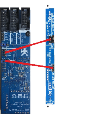
The 3rd jumper on the ART-Add-On defines the selected ART outputs 1+2 or 3+4.
You can connect 2 ART-Add-Ons in parallel to get 4 full ART channels.
Please note that the I2C port used on the Multi-IO has to be set as an output in the NerdSEQ. The port can be used in parallel with other I2C follower gear.
The I2C Ports can be shared with other I2C followers.
The ART-Add-On needs at least NerdSEQ firmware V3.0.
Sega Gamepad Expander (for Multi-IO or standalone)
This is a standalone Sega Gamepad expander. If you don’t use Midi or don’t have any Midi interface connected, this still allows the use of the Sega Gamepad features (Sega Genesis 6 Button Controller).
If you have the Multi-IO Expander, this can also be connected to the Multi-IO Thru port and adds the Gamepad features for the Multi-IO Expander.
Specifications
- Width: 4HP
- Depth: 25mm
- Connected directly into the Multi-IO or NerdSEQ with the included 12 pin ribbon cable.
34
NSA expanders
You can use up to 4 NSA expanders with one NerdSEQ. All NSA Expanders are connected to the NSA port of the NerdSEQ, either directly or daisy chained from one expander to the next.
The currently available expanders are:
Trigger16
Adds 16 more triggers/gates to the NerdSEQ. In addition to all known trigger/gate functions, there are many new functions and a nice drum-matrix screen when connected.
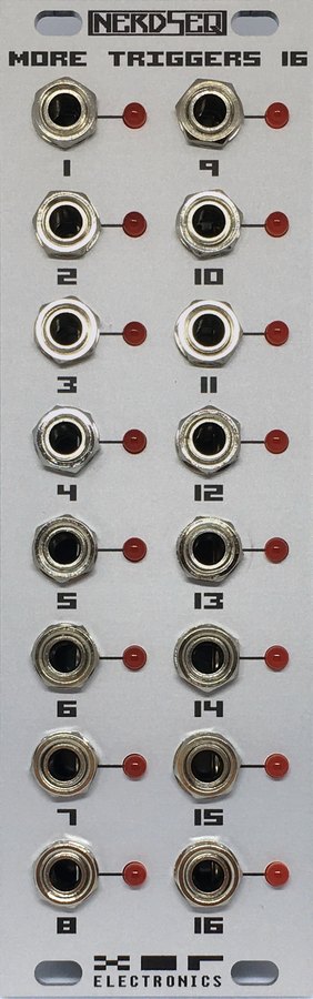
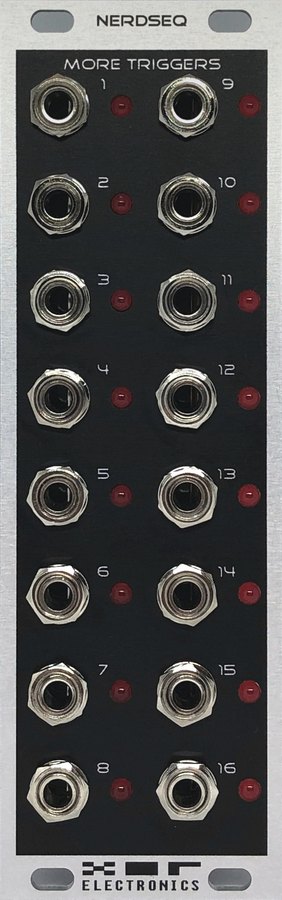
Specifications
- 16 Trigger/Gate outputs
- Output levels are either 0 or 5 Volt
- 16 LEDs indicate the output status
- Fully integrated into NerdSEQ tracks
- Power: ~30mA (+12V) 0mA (-12V) 0mA (5V)
Trigger16 Installation
Connect the ribbon cable to one of the headers and to the NSA (Nerd Sound Adapter) header on the NerdSEQ. Both headers on the expander are equal, so it doesn’t matter which one is connected. If you have multiple expanders, you connect the other header to the next expander (daisy chained) and so on.
Each expander has to be set to its own channel. It doesn’t matter which one as long as they are unique. Use the jumper on the backside and change it to the desired channel if needed.
You can freely route every channel to one or more NerdSEQ tracks. On startup of the NerdSEQ, it will detect the expander on its channel number.
CV16
Adds 16 more CV outputs for notes and pitches, as well as 8 envelopes and 8 LFOs which can be routed to any of the outputs. Additional effects per CV output.
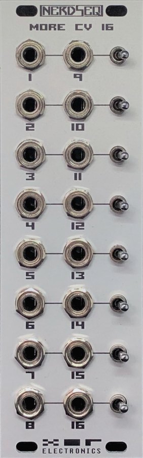
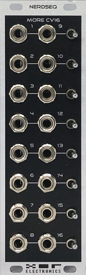
Specifications
- 16 CV outputs
- CV voltages can be pitch or note scaled
- 8 ASR Envelopes
- 8 different LFO types
- Glide settings for each CV output
- Output levels are -5/+5 Volt or 0-10 Volt (offset selector in pairs of 2 outputs)
- Up to 4 Expanders possible per NerdSEQ
- Available in black, grey or black/grey
- Fully integrated into NerdSEQ tracks
- Power: ~75mA (+12V) ~35mA (-12V) 0mA (5V)
CV16 Expander Installation
Connect the ribbon cable to one of the headers and to the NSA (Nerd Sound Adapter) header on the NerdSEQ. Both headers on the expander are equal, so it doesn’t matter which one is connected. If you have multiple expanders, you connect the other header to the next expander (daisy chained) and so on.
Each expander has to be set to its own channel. It doesn’t matter which one as long as they are unique. Use the jumper on the backside and change it to the desired channel if needed.
You can freely route every channel to one or more NerdSEQ tracks. On startup of the NerdSEQ, it will detect the expander on its channel number.
Each output can generate notes and pitches from 0 to 10 Volt (-5 / +5 Volt).
While the Notes can be used for polyphonic sequencing, all other modulations and pitches can be used to control many destinations. As is generally the case with the expanders, they can be assigned to multiple tracks.
More Video-IO
The More Video-IO Expander adds a composite and an HDMI video output to the NerdSEQ as well as a USB connector, so a USB computer keyboard can be used. Not to forget it adds also an advanced video synthesizer!
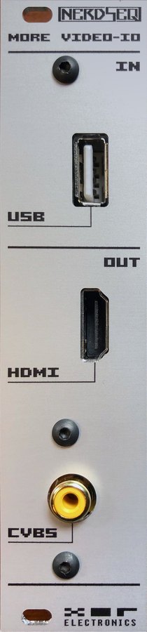
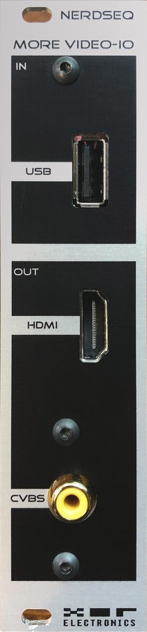
Specifications
- 6 HP width (42mm/1.64" deep)
- HDMI and composite video output
- USB Host for PC Keyboard
- NerdSEQ screen clone to bigger screens
- PC Keyboard with mapping for the authentic Tracker feeling
- Video synthesis with the use of GLSL shaders
- Expander uses fixed NSA slot 4
- Power: ~60mA (+12V) 0mA (-12V) 0mA (5V) (without USB or HDMI connected)
More Video-IO Installation
Connect the ribbon cable to one of the 14 pin headers and to the NSA (Nerd Sound Adapter) header on the NerdSEQ (or another NSA daisy chained expander). Both 14 pin headers on the expander are equal, so it doesn’t matter which one is connected. If you have multiple expanders, you connect the other header to the next expander (daisy chained) and so on. There is no channel selection on the ‘More Video-IO’ expander, but the channel is always fixed to channel 4. Please be sure no other expander uses channel 4.
Connect the other 12 pin ribbon to the Midi port of the NerdSEQ. This port is needed to get the USB connection working with the NerdSEQ. Use the second 12 pin Port to connect to one of the Midi Expanders. This port is also Daisy chained, so it doesn’t matter which of the 2 ports is used.
Please note that you have to enable the Video Expander within the Setup Screen of the NerdSEQ. From then on, it will be detected on startup.
On power-on (or expander reset), the expander detects whether an HDMI cable/screen is connected and then automatically uses HDMI mode. If no HDMI screen is connected, it will fall back to composite mode (if HDMI force is turned off, see further in the video configurations). Note that it is not possible to use HDMI and Composite at the same time. The HDMI connector is also not meant to be hot-plugged, so if possible please disconnect/connect it only when the expander/NerdSEQ is powered off.
We take no responsibility for any damage to your screen or keyboard when using the Video Expander. Please use and handle it with common sense!
In its basic use, the expander can clone the NerdSEQ screen onto a big screen. The video clone functionality is available since the NerdSEQ firmware V1.25. Video synthesis / shaders need at least firmware V3.0 for both the NerdSEQ and the Video Expander. The current and recommended version is V3.3.
In the Setup Screen you can set the Video expander to disabled, enabled with USB function only, or enabled with the clone function. Once enabled, the screen will be cloned onto the HDMI or Composite output.
The Video Synthesizer capabilities and functions are explained in the Video Track / Video Shader Functions section.
Video Expander USB Keyboard functionality
A connected Computer Keyboard (PC Keyboard) allows easier editing as many functions of the NerdSEQ can be accessed from the Keyboard directly. It can also be used to insert or play notes directly since 2 note octaves are directly mapped onto the keyboard. Notes can be played from the sequencer screen and the current track is played from the keyboard (or multiple if tracks are set to poly-midi mode). Within the tracks, notes can be played or edited using the keyboard. The 2 octaves of the PC Keyboard can also be used in the same way as a Midi Input. You can set this up in the Midi/I2C Setup screen. This allows a more streamlined polyphonic usage as well as the various record and extra Midi features.
Keyboard Layout
| Key | Function |
|---|---|
| Enter | Same as OK button on NerdSEQ |
| right ALT | Same as STOP button on NerdSEQ |
| Shift | Same as SHIFT button on NerdSEQ (use in combination with other keys) |
| Space | Same as START button on NerdSEQ |
| Tilde (~) | Edit ON/OFF. With SHIFT: Record ON/OFF |
| Tab | Toggle Automator screen parts. Toggle to CV16 functions in CV16 columns |
| Cursor Keys | Same as CURSOR UP/DOWN/LEFT/RIGHT on the NerdSEQ |
| Caps Lock | Inserts a Note OFF in the Note Columns if possible |
| CTRL+C | Toggle Mark Mode (copy to clipboard when unmarking) |
| CTRL+V | Copy/Paste (functionality and combinations the same as with the NerdSEQ buttons) |
| Delete | Same as SHIFT+DELETE on NerdSEQ (including Page UP/DOWN) |
| Backspace | Remove Pattern line and shift up |
| Insert | Insert empty pattern row and shift down |
| F1 | Sequencer Screen (with SHIFT: Track Assign Screen) |
| F2 | Pattern Screen |
| SHIFT+F2 | Scaling Screen |
| F3 | Patch Screen |
| SHIFT+F3 | Mapping Screen |
| F4 | Table Screen |
| SHIFT+F4 | Variable Screen |
| F5 | Current Values Screen (with SHIFT: Load Project) |
| F6 | Automator Screen (with SHIFT: Save Project) |
| F7 | Envelope Screen (with SHIFT: Load Sample) |
| F8 | Track Setup Screen (with SHIFT: Midi/I2C Setup screen) |
| F9 | Random Ranges Screen (with SHIFT: Video Project Screen) |
| F10 | Project Screen (with SHIFT: Sega Gamepad Mapping Screen) |
| F11 | Record Screen (with SHIFT: User Interface Screen) |
| F12 | Nerd Menu (with SHIFT: Setup Screen) |
| Left CTRL+F1..F8 | Mute / Unmute Track 1..8 (or Trigger columns on Trigger16/Multi I2C Pattern Screen) |
| Left ALT+F1..F8 | Solo / Unsolo Track 1..8 (or Trigger columns on Trigger16/Multi I2C Pattern Screen) |
| Print Screen | Load Project |
| Scroll Lock | Save Project |
| Pause | Load Sample |
| + / – on Numblock | Increase / Decrease BPM |
| CTRL + / – on Numblock | Increase / Decrease Swing setting |
| Home | Keyboard Octave +1 |
| End | Keyboard Octave -1 |
| Number Block 0..9 and Dot | Can be freely defined as a source in the mapping screen |
| Regular Letter Keys | See below (Blue: Selected Keyboard Octave. Green: Octave+1. Pink: Octave+2) |
Additionally, the ‘media keys’ of a keyboard can be used as well: MUTE, PLAY, PREV, NEXT and STOP. These 5 keys are available as mapping sources (EXT → KEYB) so you can use them for anything you like. An encoder or volume buttons, if present, are supported as well. Be aware that this might not work with keyboards that use special implementations for the media controls.
Special notes for the USB Keyboard use
- Most USB Keyboards including Bluetooth ones are compatible. However, since this is an embedded system I can’t guarantee that all Keyboards will work well. If one doesn’t work, it might be worth trying an additional USB Hub (unpowered/powered) in between.
- Many simple USB Keyboards don’t allow multiple keys pressed at the same time. This might affect you if you want to play chords with multiple notes. Please note that this is then an issue with the keyboard. This is also a known issue for many gamers who use USB keyboards, but there are special gaming USB keyboards available which solve that issue, if needed.
- Please be sure that both ribbon cables (12 pin and 14 pin) are connected well. A bad connection can cause problems on both sides: glitches in the video, problems with the USB keyboard input and/or general input problems. All other daisy chained connections, like the Midi expanders or other NSA expanders, can also cause issues if badly connected.
- Be sure you have enough ‘headroom’ with your rack power supply, as your USB keyboard might also draw extra current.
Dualchord
The Dualchord expander adds 2 times 4 oscillator waveforms to the NerdSEQ ecosystem.
Hardware specifications
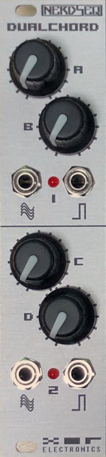
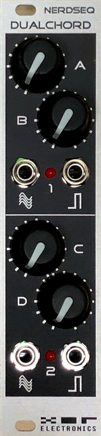
- 2 audio outputs (+- 5 Volt)
- 2 Trigger/Gate outputs (0/5 Volt)
- 4 potentiometer knobs
- 2 indicator LEDs
- 6HP, 35mm deep
- Available in black, grey or black/grey
- Power: ~100mA (+12V) 10mA (-12V) 0mA (5V)
- Expander for the NSA port of the NerdSEQ
Installation of the Dualchord
Connect the ribbon cable to one of the headers and to the NSA (Nerd Sound Adapter) header on the NerdSEQ. Both headers on the expander are equal, so it doesn’t matter which one is connected. If you have multiple expanders, you connect the other header to the next expander (daisy chained) and so on.
Each expander has to be set to its own channel. It doesn’t matter which one as long as they are unique. Use the jumper on the backside and change it to the desired channel if needed.
You can freely assign every Dualchord channel to one or more NerdSEQ tracks. On startup of the NerdSEQ, it will detect the expander on its channel number. The ‘Dualchord’ expander needs the NerdSEQ Firmware V2.02 or later. It is powered from the NerdSEQ.
General description
As mentioned, the Dualchord is a multi-oscillator module which generates 4 independent digital oscillator waveforms for each of the 2 audio outputs. Each oscillator itself runs 4 waveforms (Sine, Triangle, Sawtooth and Pulse) at the same time (that means 32 waves running at the same time!), which can be mixed independently for each individual oscillator.
Each oscillator has additional velocity, glide, detune and mix settings per waveform and pulse width settings for the pulse wave. Oscillator settings can be applied individually or combined. Morph functions allow morphing between different waveforms in every possible waveform combination. A detune spread can generate supersaw-like sounds between the different oscillators. Many convenience modes have been added to allow the use of monophonic, multi-oscillator monophonic, paraphonic or chord presets.
There is also a voice block available which adds an ADSR envelope, a filter with 19 filter types, a noise source and a wavefolder / hardsync section. This block is routed to one of the 2 outputs, while the other output is then muted. This allows a full 4-voice paraphonic synth voice which can sound like classic analogue synths.
Besides individual outputs, each with their own settings, the outputs can also be cloned, and a stereo field can be generated by de-phasing or detuning the second output. With external mixing of the 2 outputs, the 8 oscillators can be played in an 8 ‘voice’ paraphonic way.
2 Trigger/Gate outputs are available for each oscillator set, with all the trigger/gate tricks known from the NerdSEQ itself.
4 Knobs on the Dualchord can be freely assigned to any of the Dualchord functions for a direct manipulation of the Dualchord parameters (of course, everything can also be manipulated from the NerdSEQ itself).
The Dualchord also includes 8 LFOs (with triangle waveform), which also allow the manipulation of all internal Dualchord parameters. Each LFO can have its own settings for speed, phase, offset and amplitude and can be free running or synchronized to the NerdSEQ mainclock. For example, 1 LFO phase takes 128, 64, 32, 16, 8, 4, 2 or 1 steps or multiple phases (2,3,4,5,6) per step.
The Dualchord can be used for a very wide range of sounds: its oscillators can be sharp for nice acid basslines, soft for smooth sounds, massive or thin, mono or poly for multi-octave chords. Because of the many parameters it is a great drone generator, but combined with a filter and envelope it is also your cheesy 80’s analogue-ish synth pad friend. As usual, an extensive Midi integration allows for mono/paraphonic playing of the oscillators.
A Dualchord pattern screen can control all 8 oscillators directly by notes and has 2 trigger columns; all functions can be easily set up and also manipulated through the FX functions. All of the Dualchord functions can be a destination of the NerdSEQ Automators and are also available as mapping destinations.
See the function blocks of the Dualchord below:
35
Expander Firmware Update screen
You get here from the Setup Screen.
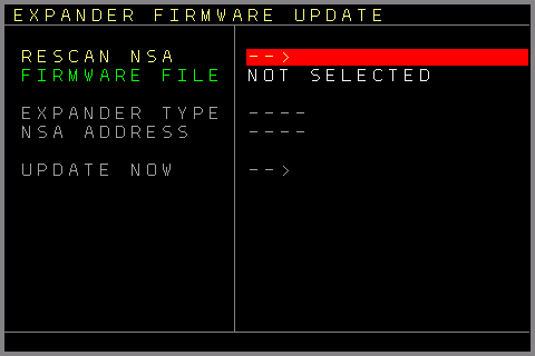
As most expanders are smart devices with their own microcontroller, their firmware might need an update for new functions or bugfixes. These expanders can easily be updated through the NerdSEQ.
The Expander Firmware update screen has the following functions:
- Rescan NSA → This will try to rescan connected expanders. This might be needed after a firmware update or if it was not recognized correctly in the beginning, or if you don’t know which firmware is running on it. Be aware that expanders should only be connected while the power is off.
- Firmware File → Opens a file browser to select a firmware file for the update. For the update, copy the firmware file into the /firmware folder of the SD card. All .nxp files are possible update files. Furthermore, a connected Video Expander can be updated too. Its file extension is .vex, and the NSA type and address are inserted automatically.
- Expander type → Shows the expander type once the expander firmware has been loaded.
- NSA Address → If available, set the channel of the expander that needs to be updated. It must match the channel which is selected with the jumper on the rear side of the expander.
- Update Now → If all is fine, Update Now can be selected. It checks whether the connected expander type is correct, among other things. On success, it starts to flash the firmware. Do not remove the SD Card or power off the NerdSEQ/Expander while updating. But do not worry if that happens anyway. If an expander is unresponsive in normal operation, you can try to flash it again. Just disconnect the power of the expander and reconnect it. You then have less than a second to press the Update now button and it will flash the expander again.
If an update is executed successfully, this is indicated and the NerdSEQ rescans all NSA expanders (if it was an NSA update). Here you can check the new version number. If something went wrong, an error message is shown and the NerdSEQ does not rescan the expanders. Try again or check out what the issue is.
Sometimes it might also be necessary to power cycle the expander before it is recognized by the NerdSEQ after flashing, even if it showed a success message.The update of the video expander looks slightly different and will finish with a restart of the video expander.
If you update the Multi-IO, the update usually consists of 2 parts: one for the main CPU and one for the Host part. The CPU part is always executed, and afterwards you can choose whether you also want to continue with a Host update. After the Multi-IO update is finished, the new Multi-IO version and Host version will be shown.
36
Scope screen (NerdScope)
The NerdScope is a built-in oscilloscope which can display up to four signals at the same time. It is handy to visualise envelopes, LFOs, CV inputs/outputs or any other value.
You reach the Scope from the Project Screen by selecting NerdScope.
The signals shown on the scope are fed to it from the Mapping Screen. Map any source to the following mapping destinations:
GLOB→SCP1..4 → Scope Input 1..4, to feed the four traces
GLOB→SCTV → Scope Trigger Input, to provide the trigger signal (reset the scope beam)
The following settings are available:
Run → starts and stops the scope. (OK to toggle)
Scope 1..4 → switches each of the four traces on or off. (OK to toggle)
Trigger Type → how the sweep is started: (X) Free running (the scope sweeps continuously), Rising, Falling or Rising+Falling edge of the trigger input.
Trigger Level → the threshold the trigger input is compared against (1 – 4095).
Timebase → the time the scope needs for one sweep across the screen: 200ms, 500ms, 1s, 2s, 5s, 10s, 20s, or locked to 64 main-clock steps.
After the main-clock setting the timebase continues into the X/Y modes: X/Y 20ms, 15ms, 10ms, 5ms, 2ms and 1ms. In X/Y mode the scope does not sweep from left to right at all. Instead it plots Scope Input 1 as the horizontal and Scope Input 2 as the vertical position, so the two signals together draw a figure, and there is no trigger. The row that normally sets the trigger level sets the length of the plotted trail instead.
The milliseconds behind X/Y are how often that figure is recaptured and redrawn. A faster rate draws a smoother, more detailed figure and costs proportionally more processor time; a slower rate leaves more of it for everything else.
37
Launchpad integration
A special feature is the integration of the Novation Launchpad (LP). It offers display and control of several of the NerdSEQ screens and functions. It works for all newer (class compliant) Launchpads including Launchpad Mini, MK2, MK3, Launchpad Pro, Launchpad Pro MK3 and Launchpad X.
All launchpads can be connected via USB using the Multi-IO Midi & I2C Expander
The Launchpad PRO devices can alternatively be connected using the regular Midi ports.
To use the LP Pro, connect the Midi Out of the expander to the Midi In of the LP and the Midi Out of the LP to the Midi In of the expander.
The LP functionality can be enabled/set up in the Midi / I2C Setup Screen settings. Beware that the LP may also listen to Midi channels other than channel 1, so Midi sequencing on channels 1..4 might interfere with the Launchpad.
Depending on the selected Launchpad and Launchpad Mode you may have to initialize the Launchpad manually. Please read the extra instruction about that in the Midi / I2C Setup Screen.
If the Launchpad is set up well, it will show the same colours as the sequencer screen, once you enter the sequencer screen again. It only really makes sense to use the LP integration with colours as you can recognise the parts very easily on the NerdSEQ screen and the LP Pads. The LP will show the upper 8 rows of the Sequencer screen and follows the scrolling of the screen.
The following pictures show the Launchpad next to the sequencer screen of the NerdSEQ. As you can see, the colours match on both, so you can easily recognize your pattern arrangements when using colours.
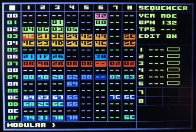
Next to the matching colour arrangement, you can see which tracks / patterns are playing. The currently playing patterns are animated and indicated as white pads. Also the current clock position is shown as a white pad in the matrix. The current step/clock position can be viewed in horizontal or vertical mode. (Change here Setup Screen)
The Pads in the matrix can be used to start the sequencer, start the pattern or to select the next pattern to play (same as the start button when on a pattern). While holding the SHIFT button and selecting a pattern in the matrix, the whole row will be started or selected to start next. (Note that in this LP explanation, the SHIFT button is the one on the LP (Button H) and not the one on the NerdSEQ.) This is also the same function as if using SHIFT+START with the normal NerdSEQ keys. The Matrix Pads/Buttons also have more functions when combined with the buttons to the right.
The top row of the LP shows the Mute/Solo buttons for the Tracks 1..8 as well as the current state of the buttons/tracks. Here green means the track is playing. Red means the track is not playing. And black or no colour at all indicates that the track is muted. You can mute/unmute the track by pressing one of the 8 top buttons. Combined with the SHIFT button, you can solo/unsolo the track.
With Buttons A and B you can scroll Up and Down in the sequencer screen. Using the A or B together with SHIFT, you can scroll a page (16 rows) up and down.
Button C combined with a Pattern pad from the Matrix will enter the Pattern.
Button D combined with a track from the matrix (column 1..8) will change the track clock scale (after the pattern is finished) in direction Dividers → Multipliers.
/7 → /6 → /5 → /3 → /32 → /16 → /8 → /4 → /2 → Normal → *2 → *4 → *8 → *3 → *5 → *6 → *7
Together with the SHIFT button, the clock scale will change in direction Multipliers → Dividers.
*7 → *6 → *5 → *3 → *8 → *4 → *2 → Normal → /2 → /4 → /8 → /16 → /32 → /3 → /5 → /6 → /7
Button E combined with a Track from the matrix will set the track clock to normal (after the pattern has finished).
Button F combined with a Track from the Matrix will select the track to stop when the pattern is finished. Pressing it twice will stop the track immediately. (same function as the regular STOP button)
SHIFT + F + a button in the matrix will stop the sequencer.
Button G combined with a button in the matrix will perform a jump to the new pattern if the selected track is playing. The jump is from the currently playing pattern to the selected pattern on the same step. (same function as using the OK button on the NerdSEQ if edit is turned off)
Together with the SHIFT button, the whole row will jump to the newly selected pattern row.
Keep in mind that these are only temporary jumps. If the pattern is finished, it will jump back to the original playing pattern.
Within patterns (either selected with the LP or with the NerdSEQ), the LP will have different functions.
In a Pattern Screen of a CV/Gate track you can insert or remove triggers. The matrix shows all 64 steps and by pressing a button you can insert or remove a trigger. Tapping Button H (SHIFT) will insert a trigger at the current playing position. Button D shifts all triggers one step UP (with overflow). Button E shifts all triggers one step DOWN (with overflow). Button F increments the triggers with the euclidean formula. Button G decrements the triggers with the euclidean formula.
The current cursor position is the euclidean start point.
In the top row you can see which track is selected.
Pressing any top button will move you back to the sequencer screen.
The Trigger16 and I2C/Multi Pattern Screens show the current drum-matrix for the first 8 or the 2nd 8 drum-matrix columns.
Within the columns you can set or reset the drum matrix triggers for the current 8 steps. The buttons on the right define the steps/rows that are selected to be edited. So top is 1..8, 2nd is 9..16, 3rd is 17..24 and so on. If you are not changing the rows, the currently selected row button will toggle between the first 8 and the second 8 drummatrix columns. The top button row is to mute/solo the triggers.
Holding any of the right buttons and pressing any pad on the grid returns you to the Sequencer Screen.
In the Dualchord screen, the notes and triggers of each Dualchord part can be seen and manipulated. The first 4 columns show the 4 notes (showing a colour if a note is inserted or blank if not), the next column shows the trigger column. These notes and triggers can be changed in the same way as on a CV/Gate track. On the right side you can switch between the different rows as well as toggle between Dualchord part 1 and part 2. This is similar to the Trigger16/Multi I2C editing.
The Midi pattern shows its 4 note columns on the pad columns 1..4, the CV16 pattern shows its 6 CV columns on the pad columns 1..6 and an audio/sample pattern shows the note and the sample slot of both voices. (Note1, Sample1, Empty Column, Note2, Sample2).
For all track types:
Notes are coloured by their note value while empty fields stay black and pad rows which carry nothing for that track type stay dark. Pressing a pad moves the cursor to that field in the pattern screen (and on the Dualchord trigger row it sets or removes the trigger), so you can change the value or dial in the value with the encoder right after that.
There are additional encoder edit modes which can be used together with the Multi-IO Expander, the PC Keyboard or via the mappings where you can assign any control as an encoder control.
One applies to Button Mode Y (on the Multi-IO). There you can select a step in the pattern screen via the Launchpad grid and turn the encoder to change the step's value. This allows nice on-the-fly dialling in of notes on the selected steps. With Button Mode Z, which allows the euclidean trigger input, the grid selects the start point/offset of the euclidean sequence.
Button Mode X is the general purpose input mode.
38
XOR Tools
Alongside the NerdSEQ hardware there is a set of web tools at https://tools.xor.eu. They run entirely in the browser, require no installation and no account, and never upload your files anywhere — all processing happens locally on your machine. Each one covers a job that is simply more practical (or even only possible) on a computer than on the NerdSEQ itself: converting an old tracker module, editing a project file as text, moving files to and from the device, or writing/changing a VEX shader with a live preview.
All of them come bundled with a nice collection of precious ultramodern themes.
Some of the XOR Tools use Midi to communicate directly with the NerdSEQ. Those need Brave, Chrome or Edge (Web MIDI may not be implemented, may be deactivated or restricted in other browsers, but it is worth searching the web for options for your favourite browser and operating system). If you connect through a regular Midi cable, both the Midi IN and Midi OUT must be connected since the connection is bi-directional. The easiest way is to use the Multi-IO expander and connect the computer to the Device port, which works ‘out-of-the-box’ if your browser allows it.
The sections below describe each tool and its functions in full.
Main Menu (tools.xor.eu)
The Main Menu is the entry point and shows you the collection of currently available tools. So far, the following tools are available:
- Module 2 NerdSEQ Converter → Converts classic tracker modules into the NerdSEQ format.
- NerdSEQ Backup → A tool to back up and restore all kinds of NerdSEQ-related files.
- Projectfile Import/Export → Converts between NerdSEQ project files and readable JSON files.
- VEX Creator → Authoring tool to create and edit your own shaders incl. browser preview.
More tools are planned to be added to the toolbox.
Module2NerdSEQ
Module2NerdSEQ converts a tracker module — MOD, S3M, XM, IT, MED, OKT and a number of other formats supported — into a NerdSEQ project file (.NRD, firmware 3.03 or later). Drop the module onto the page (or click to browse) and it is decoded immediately: you get a pattern list and a per-track arrangement grid, with a badge showing how many unique patterns the export will actually produce.
Before exporting you choose Max tracks, either 4 or 6, and can disable individual channels you don't want carried over. “Add trigger” also adds a CV gate trigger into the trigger column on every note row. Export NRD then writes the file; the download name is shortened to 8.3 DOS format, since that is what the NerdSEQ's file system expects.
Each track is exported as an independent set of patterns, so after loading the result on the NerdSEQ you are free to reorder, duplicate or chain patterns per track without it affecting the others. Keep the project limits in mind while arranging longer modules: 255 song rows, 175 unique patterns, and 64 rows per pattern.
No tracker FX, instruments or volumes are imported, since these differ too much from the NerdSEQ FX. The rest is imported ‘as well as possible’, and your notes and arrangement should be properly preserved.
The import has been made possible by using libopenmpt from the OpenMPT (https://www.openmpt.org) project, another tracker classic! Be sure to check it out and support it if you can.
NerdSEQ Backup
This tool moves files to and from the NerdSEQ over MIDI: it receives project backups and sends files back, including firmware.
It uses the Midi connection as described in XOR Tools.
To receive a backup, start the backup on the NerdSEQ itself (see Backup/Restore); each verified file downloads on its own. To send a file, drop it onto the page or use ‘Choose file…’. Accepted types are .NRD .MAP .PTN .DCP .WAV .RAW .HEX .VEX .NXP, and the NerdSEQ files each one by its extension into the matching folder (projects, samples or firmware). Press Upload and the NerdSEQ shows the incoming filename and waits 20 seconds for you to accept with START or decline with STOP. The sequencer has to be stopped first; the NerdSEQ refuses a transfer while it is playing rather than interrupting playback. An existing file with the same name is moved into a backup folder, never overwritten. Firmware updates work the same way: ‘Update Now’ (top right) stages the latest stable bundled nerdseq.hex and sends it through the identical upload flow. At the end of the upload you will be asked on the NerdSEQ if you want to update the firmware directly. Then follow the instructions.
Projectfile Import / Export
Projectfile Import/Export converts a NerdSEQ project file (.NRD) to JSON and back, byte-exactly, entirely client-side. Drop one file or many onto the page; each file's direction is detected automatically from its content, .NRD to .json and .json to .NRD, so mixed batches are handled in a single drop. Download results individually from their row, or as a single .zip once there is more than one.
Only project files from firmware version V3.03 (or later) are supported.
The exported JSON also carries a format block describing every field in plain language; it is documentation only, ignored on the way back in, and never affects the resulting .NRD. For anyone writing their own scripts or tools against this format, the JSON Programmer's Reference download bundles the full JSON schema together with the per-track-type FX command reference and more as a .zip.
VEX Creator
VEX Creator is the authoring tool for the VEX video expander that allows you to load shader animations, preview them, change them and push them directly to the NerdSEQ/VEX.
It uses the Midi connection as described in XOR Tools.
It works with two related file types:
- A .frag (or .glsl) file is plain GLSL ES 2.0 fragment shader source — code only, no images.
- A .vfrag file is the complete bundle the VEX actually runs: that same shader plus its background textures and sprite sheets, compressed, packed into one file. Both are valid things to work with; which one you load changes what comes with it. Loading a .frag replaces only the shader code and leaves whatever textures and sprites are already loaded untouched, which makes it the right choice while iterating on shader code alone or sharing code independently of its artwork. Loading a .vfrag replaces the shader and every texture/sprite slot at once: a full VEX project file.
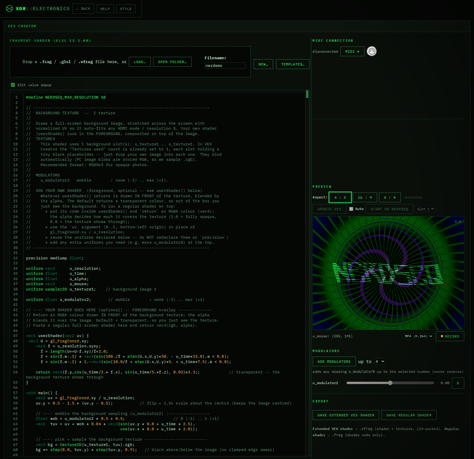
The Editor
The editor pane on the left is a full code editor; the preview on the right recompiles automatically about two seconds after you stop typing or editing and shows a red ✕ if the shader fails to compile, without losing your edits. ‘New…’ resets to the default shader with no textures or sprites (it asks first, and cannot be undone); ‘Templates…’ loads one of the bundled example .vfrag files as a starting point. Several basic demos are included there which describe the use of textures and sprites in the shader code.
Besides basic text editing, there are some neat functions integrated into the editor. While editing, a full syntax check runs which directly shows you an issue in the shader code (only one at a time). If the option ‘Edit value popup’ is enabled, some extra functionality can be opened depending on the code/values beneath. Click on any number (float, integer, vector):
1. Scrub the number directly
Drag left/right on the scrub control to change the value in place (±0.01 per pixel of drag). The shader recompiles live as you drag, so you see the effect immediately. For a vector, you can edit it either as single values, 2-dimensionally (vec2) or via a colour picker (vec3).
2. Turn it into a modulator
Instead of a fixed number, you can drive the value from one of the shader's u_modulator inputs (the same ones the modulator faders below the editor control). When you assign a modulator, the popup builds an expression from three parts:
- Offset: a fixed base value (here 0.96)
– Scale: how much the modulator's ±1 range multiplies onto the value (here * 2.0)
– Modulator: which u_modulator slot (1–16) drives it
Once assigned, a small slider in the popup lets you preview-drive that modulator's value directly, moving both the on-screen fader and the live shader preview together. The needed uniform float u_modulatorN; declaration is added to the source automatically.
– The presign (+ or -) lets you calculate the offset plus or minus the modulator factor.
3. Re-edit an existing modulator expression
Clicking a number that's already a modulator expression (rather than a plain constant) reopens the popup with the offset/scale/modulator fields pre-filled from that expression, so you can adjust it instead of starting over.
4. The popup stays open until you explicitly choose:
– Apply — keeps the edit
– Cancel — restores the exact original text, and if a modulator declaration was only added for this edit and isn't used anywhere else, removes it again
Shader editor: modulator popup
5. Tilemap / Sprite Picker popup
Click on the vex_tile title (name of the array) which opens the tilemap grid. This is the grid to which you can assign sprites. Choose one of the fields and the sprite picker opens, where you can choose a sprite for this tilemap field. You can also click a sprite-index number inside a vex_tile[…] = <n>.0 assignment to open it.
The Visual atlas grid shows every sprite currently loaded into the atlas as a thumbnail grid (if the atlas is filled with sprites), each cell numbered to match the atlas's own numbering (the same numbers you see in the sprite atlas panel).
Background textures
Select up to four texture slots (u_texture1…u_texture4) where each takes one dropped image; pick RGB565 for an opaque background or RGBA where you need transparency. Images larger than 1024 px on either axis are scaled down automatically, aspect preserved, to the VEX's hardware texture limit. The invert button (right bottom) on a texture or sprite thumbnail flips its colours. The colour picker button (left bottom) lets you pick an alpha colour which will be treated as transparent. Different settings are available to change its size or ratio. Ready-made texture blocks can be saved and loaded so you can repeatedly integrate them into your different animations.
Sprite atlas → This is where you build the set of sprites (u_sprites) your shader can draw from — up to a 16×16 grid of individual images packed into one atlas.
Grid → chooses how many sprite slots are active: none, 1×1, 2×2, 4×4, 8×8, or 16×16.
Sprite size → sets the resolution each sprite is stored at inside the atlas (16×16, 32×32, 64×64, or 128×128 px per cell). Options that would push the atlas past the 1024 px overall size limit are grayed out automatically.
The Format picks the pixel format the atlas is stored/exported in (affects whether transparency is available — see chroma-key below). Click (or drag an image onto) a cell to load a picture into that slot. Empty cells stay transparent in the shader. If a loaded image has no transparency of its own (a flat background, e.g. a solid-colour PNG), a colour picker button appears on that cell (bottom left). It lets you pick an alpha colour which will be treated as transparent.
A global transparency colour picker (for all sprites together) is also available.
The invert button (bottom right) lets you flip the colour. You can import a complete tilemap which would fill the grid in one go. One more option is to import animated GIF clips. It automatically changes the grid to the needed number of frames (or evenly skip frames to fit into the 16×16 grid).
Save and load your sprite atlas so it can be used for multiple shaders.
Both the texture (.tex) and sprite atlas (.spr) files are known to the VEX and you can use these as well if the filename matches the shader filename on the VEX SD card.
Preview
The preview shows the current shader animation. Note that it is probably not 100% identical to the final result. Different resolutions, screen ratios and slight differences in the OpenGL implementations can cause slight differences. Overall, the results are equivalent. The aspect selection lets you choose a ratio similar to the screen connected to your VEX. Next to it, the progress bar shows the time until the preview is updated (for example after updating the code). The Update VEX button also lets you update the VEX directly. Depending on the size of the textures/sprites, the upload can take a while. But that is only initially; once the latest data has been uploaded, only changes are sent. You can enable the Auto function which would automatically update the VEX as well. Keep in mind that for the live update the NerdSEQ must be in the Video Project Screen. The ‘Start on NerdSEQ’ option lets you start this shader in the selected slot automatically, so you don’t have to browse the shaders after uploading.
A left mouse click in the preview screen changes the u_mouse vector. A right mouse click opens the context menu which lets you save the current preview screenshot.
Record, below the preview, captures exactly what the preview plays — including modulator moves and u_mouse drags — to MP4 (H.264) on recent Chrome/Edge or WebM otherwise.
‘Add modulators’ lets you add new u_modulators which you can use in your code (automatically inserted). These can be manipulated directly and even assigned to a Midi CC Controller (learn function on the left side).
Finally ‘Save Extended VEX shader’ saves the complete bundle, shadercode, textures, sprites, most settings into one .vfrag file. This can be loaded again to continue editing or to put and use it on the NerdSEQ.
‘Save regular shader’ saves only the classic .frag without the texture or sprite info.
39
Calibration
Calibration and testing of all inputs and outputs.
The NerdSEQ is ‘factory’ calibrated and the settings are saved in an EEPROM. For a proper calibration you need a good multimeter, though in most cases a normal, cheap 3.5 or 4 digit multimeter will do the job. You also need a small screwdriver to be able to adjust the potentiometers on the backside.
Be sure that there are no automators or any other functions running when calibrating. It is best to calibrate after a reset of the NerdSEQ, so all settings are set to default.
Using Page Up/Down will jump over the different sections, so you can jump from the CV calibration to the Trigger test and finally to the manual input calibration.
To start a calibration, proceed as follows:
- Go to the calibration settings, choose the 2nd row: OUT CV1 0V
Set this parameter to 10, which will give you a small range lower than 10 for the calibration. Now connect the multimeter with the CV1 output. Set the CV Offset switch to the right position (below the CV outputs). The output should now be calibrated to exactly 0 Volt (as shown on your multimeter) by using potentiometer POTI 2 on the rear of the module (the one closest to the centre). Once it is calibrated to 0 Volt, change the Offset switch for CV to the left position which lets you calibrate the -5 Volt offset. For this, use potentiometer POTI 1 to calibrate the -5 Volt offset. When calibrated, check the 0 Volt and -5 Volt positions again to be sure they are correct. - Now you don’t need to touch the potentiometers any more, so the NerdSEQ can be placed back in the rack. Switch the CV and MOD offset back to the right position (0 Volt).
- Go to the next menu row OUT CV1 10 V. Change the value until it is exactly (or very close to) 10 Volt. After that you can proceed to the next value (9 Volt) or do an auto fill of the values 9V → 1V. For that press SHIFT+OK on OUT CV1 10 V which will interpolate all values for CV1 (9 Volt → 1 Volt). Now the values for CV1 are interpolated and you can continue with the fine tuning for these values.
- Now connect the multimeter to the MOD1 output and choose the next row in the menu OUT MOD1 (0V). Change the value until the multimeter measures closest to 0 Volt. Note that you might not be able to reach the exact 0 Volt point. Since the resolution of the NerdSEQ is 10/4095 values, the finest voltage resolution is 0.0024 volt. So the value closest to 0 with a slight difference in the 3rd and 4th digits is absolutely OK.
- Now choose the next menu row OUT MOD1 10V and change the setting until you measure exactly or very close to 10 Volt at the MOD1 output. Proceed again with all the in-between values (9V – 1V) for the MOD1 output, or interpolate first here as well (SHIFT+OK) if wanted.
- Connect your multimeter to the next output CV2 and choose the next row in the menu OUT CV2 0V and change the values again to get 0 Volt.
- Proceed with the measuring until you have calibrated all CV and MOD outputs.
- Next you can auto calibrate your inputs (after all outputs are calibrated well). For that you only have to connect the CV1 output to the CV1 input, the CV2 output with the CV2 input, the CV3 output with the CV3 input and the CV4 output with the CV4 input.
Be sure your offset switches are set to the right and no automators or any other functions are running.
Choose Auto Calibrate Inputs which gives you a short explanation of what to do. Press OK to start the automatic input calibration. - Next you could test all the other outputs. The menu settings show you the expected voltages for the outputs.
- In the top row you can find an extra save calibration option. In general, the calibration settings are saved automatically when you leave the calibration screen. A manual save is also possible in between.
- Sample testing for audio output 7 and 8 will turn on a sine waveform which can be tested on the outputs.
- Besides the auto-calibrate function for the inputs, you can manually calibrate an input together with the voltage source (for example a CV keyboard) you are using. For that it makes most sense to follow these steps:
Of course, connect the CV input that you want to calibrate with your source.
Play a low note on the source (for example C-1). Choose the offset of the CV input row (Input X 1V). In the status bar you can read which note the NerdSEQ is measuring. Change the offset until the note matches the low note you played. Try to reach the note; the number next to it should be as close as possible to zero. Play a very high note on the keyboard (for example C-8). Go to the range position of the calibration and change it until the status bar shows the note. Here too, try to get the value as close as possible to zero. Repeat this a few times until the offset and range are as fine as possible.
Do the same for the other inputs. The CV inputs will then match the source.
Without a source, you can also connect the CV outputs 1..4 to the CV inputs 1..4 again and calibrate manually. The outputs will automatically be set to either C-1 / 1V or C-9 / 9 Volt as the calibration reference. The result will most probably be the same as the auto-calibration.
40
Tips and tricks, FAQ, PANIC
Some general tips and tricks, general pitfalls and beginner issues are described here. Be sure to register on the XOR Forum for further information, questions, and more tips and tricks.
- Notes automatically set the Gate on the trigger output. There is no need to add anything to the Trigger column for this. Reset the gate by adding a [ ] (note-off) on another step in the Note column, or use the KILL command with a value for shorter gates. However, you can use the trigger commands to override automatic gating, or disable the Autogate feature in the Setup screen.
- An expander never adds additional tracks to the NerdSEQ. The number of tracks is fixed at 6 regular tracks and 2 audio tracks. The 8 tracks can be assigned to the expanders and provide additional functionality when assigned and all functions of the local tracks (if used with tracks 1..6) will still be available!
- Midi controller 78 will turn off all notes.
- Since there are multiple ways to generate button and key presses on the NerdSEQ (local buttons/keys, Sega Gamepad, computer keyboard), they can occasionally interfere with each other. In the unlikely event that a key gets stuck because of this, a shortcut can be used to release all keys. Hold the SEQUENCER, AUTOMATOR and STOP buttons together for that. You might also check whether you have either the Sega or the Video USB Clone settings enabled without the hardware being (completely) connected. This can also cause ‘ghost’ button presses. Please disable the Sega or Video functions if they are not (completely) connected.
41
Firmware update
New firmware can be reliably flashed into the NerdSEQ to fix bugs and add new features (and there are always a lot of new features!).
There are 2 ways to update the firmware. One is faster than the other but requires more manual steps.
Way 1 → (Classic fast way, needs more handling, more error-prone):
Place a new firmware file on the SD card in the \firmware folder. Make sure the file is named ‘nerdseq.hex’. Check the forum troubleshooting section if you have issues downloading the file with your browser. The latest firmwares are always available on the NerdSEQ website and on the forum. To be continued after Way 2.
Way 2 → Use the XOR Backup/Restore tool (Modern way via your computer + Midi, slower but easy and less error-prone. Needs NerdSEQ V3.03 or later)
For this you need a Midi connection from the NerdSEQ to your computer (Can be TRS/DIN, Device or Host). Using the Multi-IO with the Device port is recommended if you own a Multi-IO.
Visit https://tools.xor.eu
Check the instructions for the backup tool here NerdSEQ Backup.
Continuing for way 1+2:
When powering on the NerdSEQ / or after you did choose to update the firmware in the settings screen / or you used the backup tool, you have to press and hold SHIFT, COPY and CURSOR UP. ( Not the UP button!!! )
Keep holding the buttons until the bootloader appears and shows that it is checking the firmware file, then release the buttons. After the check the NerdSEQ shows the new software version and asks if it should be flashed. Press SHIFT if you want it to be flashed. Once NerdSEQ has finished flashing you must check the status and press SHIFT again to start up the new version. The screen will show if the flashing was successful. It is possible for the progressbar and the percentage to go over the 100%, restart at 0% and end up somewhere. (on early NerdSEQ) Don’t worry about that, if NerdSEQ indicates successful flashing then the update went well! That is only a visual glitch but the update is reliable also with the early NerdSEQ versions.
That’s it. If the flashing is interrupted for some reason (power, SD card removal), then you can simply do it again (after power up). Entering the Bootloader mode after power up will always work!
It is possible that the firmware upgrade mode shows an SD card error. This can happen if the SD card was not recognized well first try, keep holding the keys and it will usually work well on the next try which will follow automatically. No worries here, just try it again.
42
Cheat sheet
Navigation (all screens)
- CURSOR UP CURSOR DOWN CURSOR LEFT CURSOR RIGHT
- Move the cursor
- UP / DOWN
- Move one page (16 rows) up or down
Edit (all screens)
- SHIFT + CURSOR LEFT/RIGHT
- Increase / decrease a value or pattern number
- SHIFT + CURSOR UP/DOWN
- Big increase / decrease
Sequencer screen
- SHIFT + DELETE
- Insert a track stop
**on an empty slot - SHIFT + MARK
- Start marking; again: end marking and copy to the clipboard
- SHIFT + COPY
- Paste from the clipboard at the cursor (overwrites)
- SHIFT + DOWN + COPY
- Insert from the clipboard, shifting content down
- SHIFT + DELETE
- Empty the marked content / the current value
- SHIFT + UP + DELETE
- Delete marked content or the current value, shift content up
- SHIFT + DOWN + DELETE
- Insert an empty row, shift content down
- OK
- Create a new pattern
- SHIFT + OK
- Clone the pattern
- PATTERN
- Edit the pattern (OK too, if enabled in Setup)
- PATCH
- Current Values screen
- PATCH ×2
- Track Setup screen
- SHIFT + DOWN + START
- Mute / unmute the track
- SHIFT + UP + START
- Solo / unsolo the track (twice: unmute all tracks)
- SHIFT + RECORD
- Start and stop recording
- SHIFT + START
- Stopped: start playing at this row. Running: trigger the whole row (tracks not yet running start at global step 0, running ones when their pattern ends or on the main-clock zero cross)
- START
- Stopped: start this track. Running: cue it (starts at global step 0 if idle); twice: start at the next live quantise point
- SHIFT + STOP
- Stop everything (asks first, if enabled)
- STOP
- Stop the track when its pattern has finished; twice: stop at once
- SHIFT + STOP while stopped
- Stop all gates, sounds and oscillators
Pattern screen
- SHIFT + MARK
- Start marking; again: end marking and copy
- SHIFT + DOWN
- Mark all
- SHIFT + DELETE
- Empty the marked content / the current value
- SHIFT + UP + DELETE
- Delete marked content or the value, shift content up
- SHIFT + COPY
- Paste from the clipboard (overwrites)
- SHIFT + DOWN + COPY
- Insert from the clipboard, shifting content down
- SHIFT + DOWN + DELETE
- Insert an empty value, shift everything below down
- OK
- In a patch / table column: create a new patch or table
- PATCH / TABLE
- Enter the Patch / Table screen (OK too, if enabled in Setup)
- SHIFT + OK
- Clone the patch / table
- SHIFT + DOWN + START
- Mute / unmute the track
- SHIFT + UP + START
- Solo / unsolo (twice: unmute all tracks)
- SHIFT + RECORD
- Start and stop recording
- SHIFT + START
- Start the whole sequencer row (at step 0, or on the next launch point if running)
- START
- Start only this pattern; twice: at the next live quantise point
- SHIFT + STOP
- Stop everything (asks first, if enabled)
- STOP
- Stop when the pattern has finished; twice: stop at once
- OK on a note
- Pre-listen the note (also while moving up / down)
- PATTERN + CURSOR UP/DOWN/LEFT/RIGHT
- Change to another pattern, as in the sequencer
- OK on a sample number
- Open the Load Sample window
- SHIFT + OK on a note / MOD
- Browse note, pitch and random functions
- SHIFT + OK on MIDI velocity
- Browse the extra functions
- OK on an FX column
- Open the FX selector
Load Sample window
- OK
- Select the slot
- SHIFT + CURSOR LEFT/RIGHT
- Pre-listen the sample on output 7/8; again: stop
- SHIFT + CURSOR UP/DOWN
- Change the pre-listen octave
Patch screen
- PATCH
- Enter, with the cursor on a patch column / number
- SHIFT + DELETE
- Disable a value
Current Values screen
- PATCH
- Enter, with the cursor NOT on a patch
- OK
- Fire the trigger parameter
Track Setup screen
- PATCH ×2
- Enter, with the cursor NOT on a patch (or from the Nerd menu)
- OK
- Fire the trigger parameter
Project / Setup screen
- OK
- Open a submenu (parameter shows
-->)
Automate screen
- OK or DOWN
- Edit the automator values (lower half of the screen)
- UP
- Back up to the grid
Envelope screen
- AUTOMATE ×2
- Enter
- OK
- Activate a changed source or destination
Table screen
- OK
- Apply the selected chord
- TABLE + CURSOR UP/DOWN
- Change to another table
Nerd menu
- SHIFT + NERD
- Open the Nerd menu (with or without marked values)
Firmware update
- SHIFT + COPY + CURSOR UP
- Hold while powering on (or after a reset) until the bootloader shows; follow the instructions. If red errors appear, keep holding so it retries; after 3 errors, check the firmware file on the SD card
Reset
- SHIFT + SETUP
- Setup screen; enable Debug, then CURSOR RIGHT on ‘Soft Reset’
43
Disclaimer
This manual has been written with the best effort to make it complete and correct. However, there may still be issues, inaccuracies, or incomplete content. Please note that the manual always corresponds to the latest stable firmware version of the NerdSEQ. There is an archive of manuals for older versions. No claims can be made for features that appear in this manual by mistake. I apologise in advance for any problems that may arise from incorrect content or misinterpretation.
I appreciate any help improving the manual, so please let me know if something is unclear or could be improved. After all, I am a software developer, inventor, and musician, and the manual is just one of many things I work on.
Also, XOR Electronics takes no responsibility for any damage that occurs to any gear or other possessions, the NerdSEQ or your body by using the NerdSEQ. Please use and handle it with common sense.
Only the official firmware releases are supported. For modified (‘hacked’) versions or alternative firmwares, XOR Electronics cannot guarantee any help, and takes no responsibility for damage that happens through their use.